Hydraulic Brake Light Switch Failure
Investigation
Originally posted: 11 / 2007 R. Kwas, Revisions: On-going
------------------------------------------------------
Arcing Contact during "Hot Switching"
Carbonized Brake Light
Switch Contacts
Brake Light Switch Relay
"Field Expedient Engineering"
------------------------------------------------------
For those interested in a detailed explanation of why I recommend upgrading to a Brake Pedal Position activated Bake Light Switch, opposed to the original Brake Hydraulic System Activated Switch.
Brakes and Brake Lights in General:
When you apply pressure to the brake pedal, you want the vehicle to slow...sometimes you want this to happen fast (like when at the last moment, you decide against blowing through that yellow traffic light!)...sometimes slowly and gently (like when you’re taking Grandma Bessy and the ladies to the coffee klatch on Sunday afternoon). In addition to slowing the car in both cases, you want the Brake Lights showing also, to advise those behind of this (speed doesn’t cause accidents, it may contribute to them, but more so do unpredictable driver – and vehicle – actions I believe, and a slowing vehicle without brake lights is definitely doing something unpredictable to those following! See also: Clarkson is right!).
This is where the Brake Light Switch comes in...it’s supposed to turn ON the Brake Lights when we apply the pedal...to give those following an early warning that we’re slowing, before they take notice of it otherwise (like when they are about to relocate your bumper). ...trouble is, the hydraulic brake system pressure sensing switches installed on vintage Volvo (and many other!) vehicles up to the late Sixties just seem to not be too reliable (see Reference Information, Pressure Switch below)...and we're talking about the OE Bosch switches here, not some China trash!
After about the fourth time of replacing these switches on various 122 and 1800 vehicles (brake system bleeding required!), I got pretty tired of the action, and started to appreciate why the factory themselves had done away with this unnecessarily complicated design...so developed my own solution based on the much simpler mechanical “Pedal Position Sensing Switch” similar to the later factory designs.
Theory of Operation of the Hydraulic Switch: According to the markings found on an OE switch. These are rated for 1-3 BAR (15-45 PSI), so considering the hundreds or even thousands of PSI possible in a hydraulic braking system, one would expect the switch should work reliably.
Considering the range of working conditions, namely everything from slow rising and low pressure, to fast rising and high pressure, suggests that the requirements for a switch to work reliably throughout the possible range of operating conditions could get fairly complicated...and the fact that so many switches fail to function reliably, suggests that maybe it’s tough to meet all of those requirements reliably...
How much engineering and reliability can one expect to be in a $20 switch? Cutting open a failed switch answers that question with: Actually quite a bit!

Pictured is an OE switch, which failed very soon after installation, sectioned with a bandsaw in order to try to figure out how they work, and maybe once and for all, get to the root cause of the problem. [From a young age, I figured out, that much curiosity could be satisfied, by disassembling stuff...a lot of that stuff didn’t ever get put back together, but understanding how it was assembled and how it worked, or at least was supposed to work I figure, was worth the price of admission! I guess like Dilbert, I have "The Knack" ...now, I leave working equipment alone and try only to disassemble failed things in order to figure out why they failed.]
In the graphic below, the internal construction and function are clear. The beefy rubber diaphragm (green) seals against leaks from the hydraulic system (pink)...certainly important. The diaphragm is allowed to expand out under brakefluid pressure from the “wet side”, and transfer about 0.100” maximum of movement (linearly related to the magnitude of brake pressure), by way of the non-conductive transfer pin (gray), to the free-floating contact plate, (yellow, horizontal), located on the “dry side”, and which is normally held away from the surfaces of the two fixed contacts (yellow, vertical), molded into plastic (blue), by its own return spring.
One thing I immediately notice is that there is no provision for a snap or wiping action of the contacts, and the mechanism has no Hysterisis. These standard techniques for assuring reliable long-term contact function are conspicuously absent! See Reference Information, Snap-Action Switch below.
Arcing Contact during "Hot Switching":

A hydraulic brake light switch in action! Since the
contact is directly under control of the very slowly rising pressure, the arc
duration is extended.
Source: Swedish Embassy Analog Technology and Wowie Effects Laboratory
Limited (SwEATWELL).
Intended Normal Function:
Contact Closure (Making) Action: As the hydraulic system pressure comes up and overcomes the diaphragm, and the force of return spring, the contact plate is moved towards fixed contacts by way of the transfer pin (typically slowly, if in a normal, non-panic braking situation), finally completing the circuit as contact is made, but not after some amount of contact bounce and resulting arcing (the slower the contact closure, and the more current, the more arcing to be sure).
Contact Opening (Breaking) Action: Upon release of the pedal, the diaphragm returns to its rest position, and the return spring pushes the CP away from the contacts, breaking the circuit. Again, fairly slowly and accompanied again, by a certain amount of arcing.
Slow Action: All of this slow action at the contact results in a certain amount of contact bounce and arcing. [The effect is not unlike stick-welding, where an arc is struck, then electrode is slowly pulled away to maintain the arc and allow the resulting plasma to melt things. Here the arc is specifically desirable, unlike at the miniature electrical contact of the Brakelight Switch!]
This arcing is a distinct disadvantage of this non-snapping action design: Since both making and breaking actions of the contacts happen relatively slowly, much more contact arcing and carbonization can, and will, take place than if the actions were to take place quickly than with a snap mechanical action (providing a mechanical Hysteresis), or with a wiping action of the contacts (providing a cleaning action). It is easy to see that this action is also directly a function of the driver...if driver applies Pedal pressure slowly, the effect is exacerbated. This is why first-hand anecdotes such as "...my car still has the original Brakelight Switch and it works fine!" are sometimes also heard. Maybe that driver applies his brakes like Michael Schumacher heading for Turn 1 at the Nurburgring...and maybe that's why nobody wants to ever take a second ride with that driver! The point is: Slow pedal application and resulting contact closure is a demon which results in contact arcing!
Microscopic Inspection: Upon close inspection of the contact surfaces these are both found to be in remarkably good condition indicating extremely little use...in fact, one contact area (left in pix) on the CP and it’s respective mate are virtually virginal, showing zero melted metal or carbonization. BUT, the story is quite different at the other (right) contact area. Although it too shows very little use, the supporting plastic of the fixed contact has been heated to the point of melting, and bubbling up to become proud of the contact, preventing the CP it from making contact the next time (indeed, this is further confirmed by holding a straightedge across the fixed terminals...the straightedge is kept raised above the contact surface on the right contact and external switch terminals show no continuity). The actual amount of contact use, which can be deduced from the carbonization and deformation, is extremely low on this contact also, but melted plastic is still adhered next to the actual contact area, so this proves pretty well, that the CP was closed or close to its two fixed mating contacts as the melting occurred.
Carbonized Brake Light Switch Contacts:
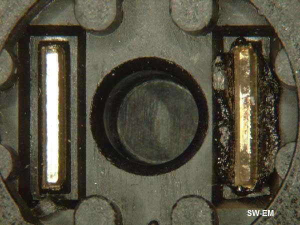
Fixed Contacts. Virginal on left, overheated, clearly
showing bubbled up plastic on right,
and an eroded, carbonized surface.

|
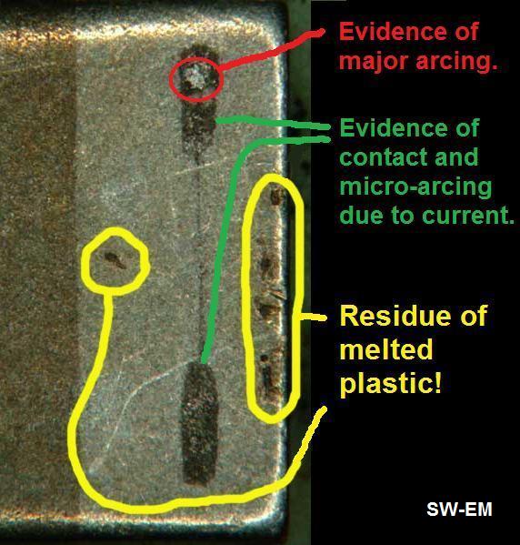 |
| Contact Plate (CP), showing absolutely virginal contact mating surface on left, with zero evidence of wear or current carrying or carbonization, and only the slightest evidence of use (but terminal!) on right! |
CP detail . Normal evidence of contact and micro-arcing due to current flow in Green. Evidence of major arcing in Red (this is likely the arc which resulted in enough heat to melt housing and bubble up molten plastic), and finally in Yellow, residue of melted plastic either side of contact line. |
Switch Failure Mode: The failure mode suggested by the theoretical analysis is confirmed. The fixed contact was definitely overheated due to arcing! This resulted in supporting plastic melting, and bubbling up with more volume, to prevent contact of current carrying surfaces.

Why this switch failed!
...so from the minimal contact use evidence, it would seem that quite soon after installation and use, maybe even the first (sloooow) gentle pedal application, the contact heated enough due to arcing, to cause the surrounding plastic bubble up...the rest, and the switch function(!), are history! Exacerbating factors causing increased arcing and heat would be particularly slow pedal application and/or having increased the load current by increasing lamp wattage, for instance by adding a third brake light.
Conclusion: Switch contact failed due to overheating, resulting from arcing due to slow contact closure, which should really have been expected! The switch may be a quality component, but from an overall engineering standpoint...this is kind-of a poor system design!
----------------------------
...so the following explanation I posted to the British Forum before doing this post mortem was actually pretty close...and I stand by it. What I would add at this point is that the hot plasma generated during arcing is causing more damage from heating than just the carbonization I originally gave it credit for, and that aging and fatigue of the diaphragm would seem to actually have little to do with the failure mechanism.
Posting Link [ http://www.volvoforums.org.uk/showthread.php?t=45938
]:
...“The pressure sensing hydraulic
switches are just not reliable...the actual electrical contact area closes under
slow-speed, low closing force...a perfect recipe for non-function from an
engineering design standpoint... it's a poor situation...the pressure comes up
very slowly during normal braking, and thus puts the switch diaphragm through a
linear (flexible) region which closes the contact quite slowly, typically not
breaking through the carbonized surface (which occurred when the contact was
last carrying current and opened), when it should ideally snap closed, breaking
through this non-conducting layer...add to that aging and relaxation of the
diaphragm, and most of the switches quit...some quite soon after
installation...add to that the unavoidable delay factor of having to make
pressure in the system in order to show brake lights, and all manufacturers
including Volvo in about '67, changed over to mechanical switches.
Regarding the "sludge" one poster found in the switch...I just can't believe
this explanation...IMO, "sludge" is not likely what keeps the switch contacts
from closing...in the first place, "sludge" would certainly transfer the
pressure to the contact diaphragm just as easily as clean fluid (I guess that
means that just as a fluid is non-compressible, so is "sludge")...further, no
"sludge" is capable of withstanding the high pressure which occurs in the
system. I believe the failure mechanism is as described above.
...bottom line IMO is to just upgrade to a mechanical pedal position sensing switch, loose all of the disadvantages, and get all of the advantages: Reliable Brake Light operation the instant the pedal leaves its rest position. You don't even need to bleed the system!”...
--------------------------
Solution Options: I’ve seen forum postings where owners have used the hydraulic switch to control a slave relay...believing that the contacts of the switch are overworked from a current-carrying standpoint. From the current-rating-only standpoint this is not the case. The contacts are sized to be easily capable of the 3.5Amps = 42W / 12V, load current (including double that for a typical incandescent inrush current), but from a systematic view, which takes into account the slow closing speed, this is actually a reasonable solution in that the current going through the contact and responsible for the heat generating arc would be greatly diminished if a relay, with its milliamps of load current opposed to brake light filaments, were the actual load on the contact. ...so I would grant, that a relay might be a solution. I would suggest that a fly-back diode be placed across the coil in order to quench the inductive relay energy which would also cause contact arcing.
Another possible solution would be to convert the brake lights themselves over to LEDs, gaining the advantage of a marked decrease in load current being switched by the contacts.
It should be noted, that although both of these solutions would seem to successfully reduce circuit current and so address the electrical issue, which would prevent arcing and save the contact, they do not address the delay due to having wait for hydraulic system pressure. Being an electrical guy, I could have simply also worked up a relay solution, but after recognizing this delay, and wanting to minimize it, and also seeing this as a way to improve the design, I chose a solution similar to the factory, and finally decided on the “Pedal Position Sensing Switch” design for myself, eventually cleaning it up and making it available for the various vehicle models as the LINK: SwEm Brake Switch Upgrade Kit.
...my advise for those who steadfastly refuse to upgrade to this superior design: Stomp on those brakes, or there’s a good chance that your brake lights are not lighting!
Silicon Fluid Compatibility Issue? Finally, at the time of this writing, I can not yet offer any explanations why the switches seem to be even less reliable in DOT5 (silicon) fluid systems (Link to Tech Article: Amazoning with Silicon Brake Fluid ). I would seem that the type of fluid on the other side of the rubber diaphragm should have little if anything to do with the failure mechanism observed and explained here. What is known, that DOT5 fluid is more compressible (at elevated temperatures)...could it be that the compressibility factor at normal temperatures is somehow contributing to the slow pressure rise and indeed causing even more of the failure mode described here? Watch this space for additional info on the subject as I develop it.
Comments as well as failed switches (for post-failure examination) are welcome. In fact, if you send in a failed switch with your order and check for a Brake Switch Upgrade Kit, you can deduct $6 from the price of the kit! This should get me a batch of dead switches with which to get some more good info. This offer is good until further notice (I don’t need that many either...I'm pretty much convinced by my findings, but it would be nice to see a similar failure condition on a few more switches...and I wouldn't mind having further support for my conclusions). Ron
-----------------------------------------------
Links:
http://www.volvoforums.org.uk/showth...light+Switches Apparently aftermarket switches are of even poorer quality and reliability (see post #8).
Info about Contact Bounce from a popular reference site: https://en.wikipedia.org/wiki/Switch#Contact_bounce
...more on "Tipping Point" from that site: https://en.wikipedia.org/wiki/Tipping_point_(physics)
My comments to a FB thread on this subject:
A
big part of the reason even OE (hydraulic pressure sensing) Brake Light Switches
fail is because the design directly applies the brake sys pressure to the
mechanical action of the internal contact, with no provision to turn the slowly
rising brake sys pressure (no fast-make/fast-break, which is always preferable
for an electrical contact to minimize arcing and contact
carbonization)...combine that with the undoubted cheapening of the contact
material in the china s**t produced replacement switches, and their failure
cannot be a surprise. See further failure analysis here:
http://www.sw-em.com/hydraulic%20brake%20light%20switches...
I highly recommend upgrading all pre late 60's vintage Volvo which still have
Hydraulic Pressure Sensing Brake Light Switches to change to a Pedal Position
Sensing Brake Light Switch, as Volvo and ALL auto manufacturers did in the late
60's for you and your passenger's safety. This also means Brake Lights come on
earlier, when Pedal is moved from its rest position, and brake sys pressure is
not even required! ...two significant safety advantages!
Full Disclosure: I sell these, in easy-install or clone of later OEM version,
but I'm not going to pay off the house with the profits any time soon! What I am
trying to do is give vintage Volvo owners a modestly priced and intelligent
alternative to this: [See
reference: Rear Ended
Amazon.]
Cheers
-----------------------------------------------
Reference Information:
Excerpt from a popular reference site: https://en.wikipedia.org/wiki/Miniature_snap-action_switch [My highlights/comments. Ron]
"The defining feature of micro switches is that a relatively small movement at the actuator button produces a relatively large movement at the electrical contacts, which occurs at high speed (regardless of the speed of actuation) [Fast Make /Fast Break!]. Most successful designs also exhibit hysteresis, meaning that a small reversal of the actuator is insufficient to reverse the contacts; there must be a significant movement in the opposite direction. Both of these characteristics help to achieve a clean and reliable interruption to the switched circuit."
Excerpt from a popular reference site: https://en.wikipedia.org/wiki/Pressure_switch [...my first Wikipedia edit - whoopie!]
"In order to apply power to the brake lights, automobiles made before approximately the late 1960s, employed a pressure switch sensing the hydraulic braking circuit, which would close with elevated pressure as a result of driver pedal application, completing the electrical circuit. After this time period, the automotive industry completely replaced these by simpler [I should have added: ...and more reliable...!] pedal position sensing switches, which can be located to close the electrical circuit as soon as brake pedal is depressed from its rest position (and before pressure in hydraulic system rises), resulting in earlier brake light function."
----------------------------
My comments to [1800list] forum suggestion to use a MOSFET to control a Brk Lt Sw Relay:
I am aware of the low ON-Resistance of mosfets, and you could certainly use
one to energize relay...almost ANY relay, making it what I would call a
mosfet switched or controlled relay...but frankly and IMO, that would be an
necessary re-engineering and complication of the circuit, because it doesn't
even address the root cause of the problem! Current magnitude is not the
issue which needs to be addressed!
The root cause of the failure is the gently rising nature of the energizing
(hydraulic) force (unless you are racing!) and the resulting
slow-make/slow-break of the electrical contact, which causes arcing and the
resulting heat carbonizes the contact, and/or melts the housing, as I have
documented in detail here:
https://www.sw-em.com/hydraulic%20brake%20light%20switches%20notes.htm

There are certainly mechanical fast-make/fast-break solutions which could have been implemented (these are typically present in industrial switches to provide hysterisis), but these would have unnecessarily raised the cost of the switches, and it would still not address the late-closing issue (needing to make Brk Sys pressure for contact to close!). The solution was clear long ago (late '60s)...and ALL car manufacturers including Volvo recognized this and changed to Pedal Position Sensing Brk Lt Sws at that time.
Since the amount of arcing is directly a function of the rate and force at which the driver actuates the Brake Pedal, this highly variable input to the equation explains why some owners (who apparently must brake like Michael Schumacher going into any Turn 1 while under challenge) report "my original hydraulic Brk Lt Sw still works fine", and some owners (who apparently apply their brakes as if they were chauffeuring around Her Majesty the Queen) only get ridiculously little time on replacement switches which they repeatedly need to replace. I believe the reason modern and currently available replacement switches don't seem to last anywhere near as long as in some cases the originally installed switches, can be explained by the typical "replacement parts are junk" explanation...which doesn't explain much, but I expect the producers of these "chinashit" replacement switches cheapened up the brass alloy contact material used in these switches, such that it is nowhere near as tolerant of the arcing which is guaranteed to occur in use, because of the slow-make/slow-break action. I have no contact material studies to substantiate that explanation, but it could be as simple as that (as it often is!).
Cheers
----------------------------
"Field Expedient Engineering" is great in a pinch, but ...don't let it come to this as a long-term solution...:

...or these two solution, based on the same principle:
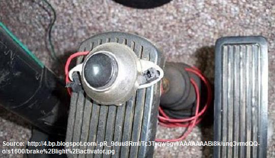
..rustic but effective! I like it!

.

See also: SW-EM Safety Bulletin 1
-----------------------------------------------
External material is attributed. This article is Copyright © 2007-2024. Ronald Kwas. The terms Volvo and Bosch are used for reference only. I have no affiliation with either of these companies other than to try to keep their products working for me, particularly the Brakelights(!), help other enthusiasts do the same, and also present my highly opinionated results of the use of their products here. The information presented comes from my own experience and carefully considered opinion, and can be used (or not!), or ridiculed and laughed at, at the readers discretion. As with any recipe, your results may vary, and you are, and will always be, in charge of your own knuckles!
You are welcome to use the information here in good health, and for your own non-commercial purposes, but if you reprint or otherwise republish this article, you must give credit to the author or link back to the SwEm site as the source. If you don’t, you’re just a lazy, scum sucking plagiarist, and the Boston Globe wants you! As always, if you can supply corrections, or additional objective information or experience, I will always consider it, and consider working it into the next revision of this article...along with likely the odd unique metaphor and (equally likely) wise-a** comment.