
FIGURE 1. 1800 Factory Wiring Diagram Extract with incorrectly shown internal connections of:
1. Light Switch, 2. Wiper Switch, 3. Fan Switch, highlighted.
Update: Color Code Errors at Wiper Switch have been corrected, see below!
1800 Light Switch, Wiper Switch,
Fan Switch Drawing Corrections
Jun 2014 R. Kwas, changes on-going (mostly when the spirit moves me)
[Comments Added]
-----------------------------------------------
Light Switch
Relay Controlled Headlights
Reference information:
1800 Light Switch
Disassembly, Review, and Reassembly
1800 Wiper
Switch Disassembly, Reassembly, and Review
Micro-Wirebrush
1800 Fan Switch
Disassembly Review and Reassembly
Reference Information
Replacement Rheostat
Parts
Selection at Agent Strangelove
-----------------------------------------------
Background: On the Volvo factory wiring diagrams of early (carbureted) 1800, the internal switching shown for Lights, Wipers and Fan switches is just plain wrong, showing in each case oversimplified connections which don’t allow for the sequential nature of each of these multi-position pull switches.
Now this is not a huge problem that would bother anyone but the writer, but it is the writer’s opinion that what is shown should be correct, making it infinitely more useful if one was engaged in troubleshooting problems involving those circuits!
FIGURE 1. 1800 Factory Wiring Diagram Extract with
incorrectly shown internal connections of:
1. Light Switch, 2. Wiper Switch, 3. Fan Switch, highlighted.
Update: Color Code Errors at Wiper
Switch have been corrected, see below!

Picture of Lucas' finest
(insert gagging sounds here!) switches in question. L to R,
Fan, Wiper, Light.
The Rheostat for Variable Instrument Lighting is located in the white ceramic
visible here.
(Fuzzy) Picture credit: Stolen from some E-Pay offer. Condition:
Gently used and abused, and sold "As-Is"!
-----------------------------------------------
1. Light Switch: The typical published Wiring Diagram shows an oversimplified switch, with Power input terminal connected to a contact arm which connects to EITHER Marker Lights (switched to the right) OR Headlights (switched to the left), suggesting this is a Single Pole, 3 Throw (SP3T) switch. That is clearly incorrect. The correct representation is sequential as shown here on the right, applying power to Marker Lights in position 1, and Markers AND Headlight (Mainbeams) in Position 2.
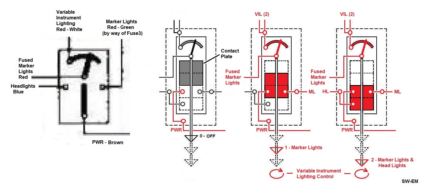
FIGURE 2. The 1800 Light Switch showing oversimplified
representation on left, and wiring color codes, taken from Wiring Diagrams...
and corrected on right, showing internal functional detail, including the sequential
connections of Marker Lights and Head Lights.
[I have added the
Contact-plate,
shown in the possible switch positions with Red
indicating nodes and functions which are powered in the
respective positions.]

FIGURE
3. Picture of an 1800 Light Switch,
once again graciously made available for my disassembly, and up close and
personal inspection, by Chris Horn (a.k.a. Agent Strangelove). See:
1800 Light Switch
Disassembly, Review, and Reassembly.

Electrical checks of Light Switch. Pos 1.

Terminal Identifications added.
The Variable Instrument Lighting is controlled by rotating the knob, as usual, but power to the Rheostat is supplied only after routing the entire Marker Lights circuit first through Fuse 3. The Fuse 3 circuit is the subject of separate consideration, as the factory fuse rating of 35A(!) is completely inappropriate. See: Proving Everything Bad you Ever Heard About Lucas.
See also: Relay Controlled Headlights
Intermittency of the 1800 VIL, and options to address this, are considered here: 1800 Variable Instrument Lighting
Replacement Rheostats are available. See: Reference Information, Replacement Rheostat
-----------------------------------------------
2. Wiper
Switch:
The typical published Wiring Diagram similarly shows an oversimplified switch.
Detailed, correct connections are shown below. Wiper System function is covered in detail
under the Wipers Tech Article LINK:
Windshield%20Wiper%20Systems.htm#Different_Motors_and_Different_Circuits

Early 1800 Wiper Switch, showing the typical Red, Green, Black harness running of
to the Wiper Motor Assembly.
This is actually inconsistent with the color
codes shown on the Wiring Diagram Excerpt below, and needs to be checked!
Update: The Three wires going into the harness running off to the Motor
Assy are correct and typical as seen in the picture above
...the wire marked GUL (Yellow), on Wiring Diagrams should be labeled Green, it is the wire
bringing power to the
Park Switch of
Motor Assy, and the wire marked Green, should be marked Red(Röd) These corrections
are shown below.

1800 Wiring diagram Wiper Switch extract, including Color Code
Corrections of
the originally (oversimplified!) published
factory diagrams,
and fully detailed and corrected version showing sequential switch internal
connections, and correct color codes!
For a detailed inspection and review of the Wiper Switch, see below: 1800 Wiper Switch Disassembly, Reassembly, and Review
-----------------------------------------------
Finally, the Fan Switch, again is shown oversimplified and incorrectly. The correct representation is really as shown also in the 122 factory Wiring Diagram, showing connections which are sequential as the 3 position switch is activated, to allow for two speed operation.

FIGURE 3. Fan Switch wiring detail.
Oversimplified and incorrect excerpt from 1800 Wiring Diagram on left (maybe
drawn by some Lucas employee doing his part to kill the British car
industry). The correct excerpt from the 122 wiring diagram on the right, drawn by a Swede
who was paying full attention, and the combination of the two by the author
[also paying attention!], showing
correct details.
---------------------------
Links:
Amazon Lightswitch Review and Notes
Variable Instrument Lighting for 1800
--------------------------------------------------------
Reference information:
1800 Light Switch Disassembly, Review, and Reassembly:
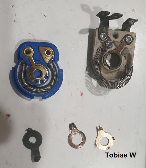
Disassembly:

Tabs of the switch housing are gently bent back to allow disassembly.
Sub-components are carefully removed (there are springs(!), so these need to be
gently decompressed, to prevent firing components around the shop, and causing
elevated levels of stress and profanities). Here, the cleaned individual
components are laid out for inspection.

The variable Resistor (Rheostat) used for the
Variable Instrument
Lighting is located and supported by the ceramic form between knob and
actual switch housing (this is a retired switch which was taken out of service,
and Rheostat is not complete or intact). A date of manufacture of 11 '61
is apparent.

Manufacturer's name is apparent (excuse me while I gag!)
All parts are found to be in decent, reusable condition.
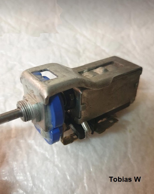
Reassembly:

The switch position/station detents are provided by dimples in the housing, into which
a spring-loaded ball-bearing located in switch Shuttle, rolls.
ACZP is has a grease base, so in
addition to being an excellent anti-corrosive, it is applied here to make use
of the lubrication properties of the grease component.

Pin-point application of ACZP in the holes in Shuttle, which locate springs,
that preload movable Contact-plate into fixed contacts on Bottom Plate.

Three Springs have been returned to their holes in the Shuttle. Formed copper Contact-plate is held next to its final location in the assembly.

Contact-plate in its normal location on the Shuttle (and in Position 0 - OFF). Springs in the Shuttle are relaxed and uncompressed.

Switch ready to receive Bottom Plate which has molded-in, fixed contacts. The
contacts exhibit some indications of wear, but are in generally acceptable
condition. Contact areas where Contact-plate dimples will slide, have also been
lubricated with a bit of ACZP.

Bottom-Cover of switch is placed in position, compressing contact springs, and temporarily held in-place with a wire-tie, allowing the switch to be test-cycled and checked. Once satisfied with the mechanical switch action, tabs securing Bottom Plate in place are gently bent back into place to hold the assembly together.
This Light-Switch is now ready to be returned to service, but since the Rheostat part is no longer intact, Instrument Lighting would have to be addressed, separate from the Switch. See: 1800 Variable Instrument Lighting.
Review: As I noted during review and refurbishing of the 122 Light switch, which is an impressively high quality component, the 1800 Light Switch is only of an adequate level of quality...it's OK, but it doesn't even travel in the same quality universe as the 122 Light Switch!
------------------
1800 Wiper Switch Disassembly, Reassembly, and Review:
Disassembly:


Early 1800 Wiper switch by Lucas, after superficial cleaning, ready for a SW-EM
evaluation. Date of manufacture of 4/62 is clearly evident, as is a
non-factory hole in one of the terminals(?).

Housing tabs are gently opened, to allow disassembly.

Internal construction principle is quite similar to the Lightswitch, with a
spring-loaded Contact-plate making connections with copper contacts molded (?)
into bakelite switch base, based on Knob and shaft position in the housing.
The sliding action of the Contact Plate assures a cleaning action of the
contacts. Position detents are provided by a ball bearing, in the bakelite
shuttle on the opposite
side from the Contact Plate, spring loaded into depressions in the Housing. An additional isolated contact as a function of Knob turning is
located outside of the main Housing, and highlighted here in
Green.
Internal Connections: Upon disassembly, the shape, of Contact Plate, and position of contacts on Base Plate, including witness marks in the lubing grease, make documenting the somewhat complicated connection in the three Knob Positions possible.

Functionally identical to the 122 Wiper Switch, the Green wire supplies Ign
Power to the Switch as well as Motor Assy.


Disassembly is straightforward, showing the remains of a generous application of
grease on moving parts as well as contacts. The grease has gummed and
jellified somewhat, but is actually not terrible...cleaning it away and
replacing it will go a long way to making the mechanical action smoother.

Alcohol wetted cotton swabs are fine for cleaning away old grease, after a full,
careful disassembly. The Shuttle lifts off the Shaft, which then can be
fully withdrawn. The shaft and its bushing are cleaned and lubed as well.

After a good cleaning and inspection, where no damage and only modest wear is
found, all components are again well lubricated (with
ACZP, making use of its grease base), and ready for Reassembly.
Reassembly:
Base of switch is placed in position, compressing contact springs, and temporarily held in-place with a wire-tie, allowing the switch to be test-cycled and checked. Once satisfied with the mechanical switch action, tabs securing Bottom Plate in place are gently bent back into place to hold the assembly together.

Checks on the Wiper Switch after refurbishing, and reassembly.
The only possible improvement the author can see would be to address long-term corrosion effects at the riveted contacts of the interconnecting strap on the base contacts. If any corrosion between these connections develops, it could affect service. A preventative measure would be to clean the rivet and strap, and solder these, making a long-term Gas-Tight-Joint.

Riveted terminals are cleaned up up with a homemade Micro-Wirebrush (a mini-collet
handtool with short length of 1/16" SS aircraft cable supplying the bristles!). Trying to
solder without preceding this operation without such a thorough preparation,
would be impossible(!), as the corrosion and contamination of decades would make
it impossible for the solder to make a molecular bond with the base metal,
(Reference:
SW-EM
Soldering Notes ) but the Micro-Wirebrush prep cuts through/eliminates
all of surface corrosion, leaving a virgin shiny metal surface, so allows
unifying the internal
contact with external terminal stack, by
soldering, making a Gas-Tight-Joint!
...and upon closer examination, the reason for the non-factory hole in the bottom right terminal (Yellow), also becomes clear...the last terminal in the stack had partially broken away at some point (remainder of the terminal is actually still present and visible under the rivet! (Orange)), leaving a precarious mechanical condition and no place to plug a wire! ...maybe the switch had previously been "serviced" by some hamfisted mechanic who was more used to working on bigger, beefier parts on Corvettes. In any case, the industrious and creative repairer drilled and tapped a hole for an additional screw and ring-terminal to receive the homeless wire (when he of course could have just used a paralleling terminal, of the type shown here):

Source: https://www.mouser.com
...but as they say about skinning a cat...
Soldering all the stacks into monolithic structures, is a good idea electrically, and also a particularly good idea mechanically for the compromised stack of terminals!
Review: The Lucas Wiper Switch of the early 1800 is an OK design with good margins built-in to allow for trouble-free operation for a long time. The switches lend themselves well to refurbishing, and when this is undertaken, a reliability upgrade/preventative by soldering terminals is suggested.
------------------------
Replacement Rheostat: Tobias Widmer informs that Replacement Rheostats are available for rebuilding Lucas Light Switches, from Moss Motors (who I have no relationship with!), PN: PI 207134, 146-000, BHA 4278
Pictures shown with his kind permission.
Replacement Rheostat with which a defective Light Switch Variable Instrument
Lighting can be repaired.
Parts Selection at Agent Strangelove (aka Chris Horn):
When I contacted Chris looking for early 1800 Wiper and Fan Switches to disassemble and inspect, he sent me a picture of his sizable selection:

Chris Horn Picture used with his kind permission.
He was able to provide these very reasonably priced parts from his stock of used parts in a timely manner...and now the reader knows why I recommend him for used parts for 1800s and 122s, and why I go to him myself. Thanks Chris! [agent_strangelove AT hotmail DOT com] [and no...he isn't my brother in law!]
--------------------------------------------------------
External material attributed. This information is Copyright © 2014-2026 Ronald Kwas. The terms Volvo and Lucas are used for reference only. I have no affiliation with the former, other than to try to keep its fine vintage products working for me, and to help other enthusiasts to do the same, and to give the later all the grief they've earned and deserve! (See: Proving Everything Bad you Ever Heard About Lucas ) The results and information presented here are my own experience, and highly opinionated impressions, and can be used or ridiculed and laughed at or worshipped, as you see fit. As with any recipe, your results may vary, and you are, and will always be, in charge of your own knuckles, and future!
You are welcome to use the information here in good health, and for your own noncommercial purposes, but if you reprint or otherwise republish this article, you must give credit to the author or link back to the SwEm site as the source. If you don’t, you’re just a lazy, scum sucking plagiarist...so the Boston Globe wants you! As always, if you can supply additional objective info or practical experience, I’d appreciate hearing it, and will consider working the information in to the next rewrite of this article...along quite possibly with the odd wise-a** comment, if I can possibly work that in.
