Picture source: https://www.tauschticket.de/Fachkunde_Kraftfahrzeugschlosser_16926106/
Bosch Generator based Charging
System in Detail
Oct 2015 R. Kwas
----------------------------------------
Cut-Out Contact
Voltage Regulation
Links:
Difference between
Voltage and Current Regulation
Changing Brushes
Separate Tech Article on Cut-Out Contact
Cut-Out Contact Notes
----------------------------------------
I have found this theory of operation / functional explanation of Generator based Charging Systems (totally applicable to Bosch Systems) to be the absolute best I have ever run across. It is by Josef Scholz, an automotive electrical specialist and avid motorcyclist using material originally from the now antique book: Fachkunde Kraftfahrzeugschlosser (1964; VEB Verlag Technik Berlin), which he probably used in Mechanic's School...and which is apparently still available, proving well presented, good information, never goes out of style!
Picture source:
https://www.tauschticket.de/Fachkunde_Kraftfahrzeugschlosser_16926106/
I have contacted Mr Scholz with my thanks for republishing excerpts of the material, complimented him on his additional explanations, and request for permission to republish and translate it. The Original, and his remarks are in German, but it's so good, that I had to leave it unchanged (including his first person notes, and except for several minor corrections), only Translate it and include it here, along with my Notes where I had something to add.
Comment: There's a lot happening in your Regulator! ...and it's all done with magnetism!
| Original, as located here: http://www.kfz.josefscholz.de/Gleichstrom-Lima.html | Translation: | Notes: |
 |
Gleichstrom-Lichtmaschine: Feldwicklung: Bürste: Brush
|
It's called a Direct Current Generator to differentiate it from an Alternator, but both actually generate Alternating Current (AC), because both function by varying magnetic force cutting through a coil (through spinning). However, both put out DC because both have provisions for internally rectifying the generated AC to DC output. Generator: Field is typically housing, and output current flows through Brushes which by their location on Commutator achieves rectification to DC (mechanically). Alternator: Field is typically doing the rotating (supplied by slip rings), and output is taken from windings on the housing, and rectified by solid state diodes. |
 |
Function of a
3-Contact Regulator 1. What does the Regulator do? The Regulator has two duties in a
vehicle electrical system: |
|
 |
2. The Cut-Out Contact Theory of Operation of Cut-Out Contact: See also: Cut-Out Contact Notes |
|
 |
Voltage Coil (5) is connected directly across the two connections of the
Generator. The magnetic field generated by this coil, is directly
dependent on the output voltage of the Generator. At the point
where magnetic force overcomes Spring (Feder) force, the electrical
(Cut-Out) contact is pulled closed. In this manner, Generator
output is connected to Power Buss, supplies Loads, and charges Battery. Once Cut-Out Contact is closed, current flowing through Current coil (2) increases the total magnetic force of generated by Voltage Coil (5) such that contact remains tightly closed. Kontakte: Contact Durchfluss der Spannungsspule: Current of Voltage Coil Contact is closed (magnetic field pulls contacts together), Generator voltage drops below Battery voltage (reverse current flows) |
Notes:
Positive Feedback! This provides Hysteresis! See Reference 1.
Since no difference is apparent between drawings 2 and 3, I believe they forgot to change drawing 3 to illustrate what is stated in text. |
 |
If Generator Output Voltage drops below Battery voltage with
decreasing engine RPMs, a current flows from Battery to Generator
(reverse direction). Since direction of current in the Current coil is now in the opposite direction, the magnetic field which closes the contact is weakened, eventually to less than the Spring force, opening the contact and disconnecting Generator from the Power Buss. If the Cut-out contact were to stay closed, current would flow from Battery to Generator, discharging Battery Whoever opens their Regulator and doesn't recognize anything, an explanation of function follows. To determine if the Voltage is sufficient, a clamp-on Amp meter (or Current probe, see Reference 2) can be used. These are available from various commercial sources, suitable for AC or DC, and have the advantage that unlike a current measurement where circuit must be opened to insert a Shunt, such as permanent current measuring installations, a clamp-on current probe may simply be clamped around a conductor (while circuit is energized and current is flowing), and current can be read directly. |
|
 |
3. Principles of Voltage
Regulation In order to understand Voltage Regulation, it should be understood how current is generated in the Generator. Field Coils are incorporated in the Housing of Generator. These are energized by the vehicle power buss, thus generating a magnetic field. Rotating in this static magnetic field is an Armature, and in this manner, current flow is induced in the rotating Armature, and conducted away by the Brushes. The generated Voltage is determined by two factors: - Armature rotational speed (RPMs). The Voltage Regulator holds the system voltage constant by varying the Field Winding Current. |
|
 |
Three Field Winding Switching Conditions
Exist
A. Field Winding is connected to power buss. Maximum current
flows and maximum Generator output is generated. Power bus voltage is held constant through rapid adjustment of these three control conditions. There can be two types of Regulators. One which controls the positive side of the Field, another which controls the negative side of the Field to chassis. |
Notes:
This is a general statement of explanation. Volvo's have a Negative controlling Regulator |
 |
4. Regulator in Detail It should be noted that there are many versions of Regulators. All function similar per the described principles. For simplicity, a three-contact, negative field controlling Regulator is described here. |
Notes:
As found in the Volvos! |
 |
Generator Turning at Low Speed Cut -Out
Contact. Regulator Contact. Field Current circuit is shown in Red. Contacts RK1 and RK2 are closed. As such, DF is directly connected between Power Buss (by way of AMP Indicator) and Chassis. Generator puts out maximum Voltage. Note: The connection between Terminals 51 and 61 at Regulator is by way of the Ignition Switch. From Term. 51, Battery Power is connected to Ignition Switch. From Term 15/54 (Ignition, Brakelight, AMP Indicator) it continues on to AMP Indicator. Other side of Indicator is directly connected to Term 61. |
Notes:
Added in Green to all subsequent
drawings: ZündStromVerbraucher (ZSV): Ignition power Loads BatterieStromVerbraucher (BSV): Battery Power Loads |
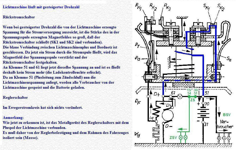 |
Generator Turning at Elevated
Speed Cut -Out Contact As voltage produced by Generator rises with elevated RPMs, so does the magnetic field of the Voltage Coil, such that the Cut-Out contact closes (SK1 connected to SK2). Shown in Blue is the closed connection between Gen D+ and Power Buss. As current is flowing through the Current Coil, the magnetic field is increased, and the Cut-Out Contact is held closed at an reinforced level. Term 51 and 61 have the same voltage, no current flows (AMP Indicator remains OFF). Since Term 51 is connected to Generator output, all Loads are supplied by Generator, and the Battery also gets charged. Regulator Contact Nothing has changed from previous condition, and contact remains closed. Note: It can be recognized now, that frame of the Regulator Contact is connected to Battery Positive, Voltage Regulator must therefore be isolated from vehicle frame (chassis). |
|
 |
Generator Speed climbs further
Cut -Out Contact Since Generator output continues to increase, the Cut-Out Contact continues to be tightly closed. Regulator Contact Generator output voltage increases due to the high RPMs to a high level. This results in the magnetic field of the Voltage Coil attracting and moving the RK2 contact, such that the connection to RK1 opens (but is not connected to RK3 either). The direct connection to Chassis is thereby interrupted but flows instead, at a reduced level, shown in Red, through the regulator Resistance (Wd, which is connected to Chassis). With this decreased Field Current, Generator output is reduced.
|
|
 |
Generator Speed is Very High
Cut -Out Contact Since Generator output continues to be high, the Cut-Out Contact continues to be tightly closed. Regulator Contact The magnetic field generated by Voltage and Current Coils is so strong, that moving Contact RK2 is connected to RK3. Since RK3 is also connected to D+, a connection is made across the Generator Field winding, shown in Red. Without Field Current, the Generator theoretically cannot produce an output.
|
|
 |
Generator Speed drops sharply
(Generator Voltage is less than Battery Voltage)
Cut -Out Contact Since Generator Output voltage is less than Battery voltage (reverse) current now flows into the Generator, shown in Blue. Since the Magnetic field of the current coil also reverses, the total magnetic field is reduced, resulting at some point in the Cut-Out Contact opening. Note: The AMP Indicator only goes ON, after the Cut-Out contact opens, since the Lamp of the Indicator is equivalent to a resistance. Regulator Contact The Magnetic Field produced by Voltage and Current Coils is weak, and Field Coil once again is connected to unreduced Power Buss. |
|
 |
5. Combined Voltage
Regulation For those that haven't had enough, here is an explanation
of Combined Voltage Regulation. During charging of the Battery,
neither Voltage of Current may be too high. The Voltage is held
constant as explained above. Determining the Charging Current
takes a bit of Physics: If you are riding around with your MZ (a 6V motorcycle) with
Lights ON, you are consuming 60-70 Watts (Front Light 45W + Rear Light
5W + Ignition 10-20W). It can be seen that Current is a factor of Loads in use (Radio, Subwoofer etc.). Unfortunately, this is also the Charging Current which the Battery receives. Combined Voltage Regulation means that the combination of Voltage and Current Coils on one Iron Core results in regulating not only the Generator, but also the Current flowing through the Current coil has an influence. A high current also increases the magnetic field of the Iron Core. This means that with too high an output current, the Field is also reduced. Source: (Drawings and parts of Text): Fachkunde Kraftfahrzeugschlosser (1964; VEB Verlag Technik Berlin) |
|
1.
https://en.wikipedia.org/wiki/Hysteresis#Magnetic_hysteresis
2.
https://en.wikipedia.org/wiki/Current_clamp
----------------------------------------------
My explanation of the Difference between Voltage and Current Regulation asked here: https://www.volvoforums.org.uk/showthread.php?t=286987
"Voltage Regulation is when the VReg monitors system voltage and when low, enables Charging System to generate and contribute power...which pulls up system voltage as it recharges Bat and powers loads. Current Regulation is rather a safety function of the VReg...it monitors the Gen output current and if too high (so that it might damage Ch Sys) it has the ability to decrease the (Field) energization current, which in turn, backs down the Gen output and lowers the stresses put on it...it may therefore take longer to recharge a highly discharged Bat, but that is always preferable to overloading the Gen and risking damaging it..."
A good explanation of Generator operation referenced in that Thread: https://www.volvoforums.org.uk/attachment.php?attachmentid=115938&d=1538325276
Good info (VW) on Brushes and changing them: http://www.reluctantmechanic.com/step-by-step/change_generator_brushes.php

Volvo PN 273500 Generator brush. Picture kindly provided by Derek
of the British Volvo Owners Club.
----------------------------------------------
External material sources are attributed. Otherwise, this article is Copyright © 2015-2023. Ronald Kwas. The terms Volvo and Bosch are used for reference only. I have no affiliation with any of these companies other than to try to keep their products working for me, help other enthusiasts do the same, and also present my highly opinionated results of the use of their products here. The information presented comes from my own experience and carefully considered opinion, and can be used (or not!), or ridiculed and laughed at, at the readers discretion. As with any recipe, your results may vary, and you are, and will always be, in charge of your own knuckles!
You are welcome to use the information here in good health, and for your own non-commercial purposes, but if you reprint or otherwise republish this article, you must give credit to the author or link back to the SwEm site as the source. If you don’t, you’re just a lazy, scum sucking plagiarist, and the Boston Globe wants you! As always, if you can supply corrections, or additional objective information or experience, I will always consider it, and consider working it into the next revision of this article...along with likely the odd metaphor and probably wise-a** comment.