
1800E Instruments at Idle!
D-Jet Idle Adjustment
First Published Sept 2022, R. Kwas [Comments added]
Idle Adjustment Screw
Setting Throttle Stop and TPS
1. Setting Throttle
Stop
2. Setting the TPS
3. Setting the Idle
Aux Air Valve Influence on Idle
Links
Throttle Valve Switch
Service and Maintenance
Timing issue causes Idle
inconsistency
Reference Information
Throttle
Position Switch Detail
The Edge Triggered Flip-Flop
TPS Terminal Locations
D-Jet Throttle Position Switch Suggested
Maintenance
Baaad Info
http://www.sw-em.com/bosch_d-jetronic_injection.htm
Note: All occurrences on Throttle Positions Switch or its TPS abbreviation have been, or are slated to be changed to Throttle Valve Switch (TVS) to be consistent with Volvo and Bosch documentation.
-----------------------------------------------------
1800E Instruments at Idle!
Idle adjustment on vehicles with D-Jet can be as simple at the very minimum, as diddling the Idle Adjustment Screw, but...that presumes a number of influencing factors and adjustments are correct! If this is the first time one is making an idle adjustment, where those factors are uncertain or unknown, or one just doesn't want to make such presumptions, here is a full process with explanations, because simply adjusting the Idle on the Bosch D-Jet Injection System has multiple prerequisites!
First, it should be performed only after Valve Clearance and Ignition settings are known to be at nominal condition!
Second, it should only be done when engine is warmed up and TStat has opened...before that, during warm-up, a functioning Aux Air Valve allows the bypassing of some air past the Throttle to raise the Idle to "Fast Idle". In fact, with all the air hoses and their connections associated with the AAV, which can heavily influence the Idle, wreaking havoc with any adjustment or its affect on the Idle including consistency and repeatability, it is advisable and good practice to eliminate the AAV and those associated connections from the equation entirely before trying to make Idle adjustments, because as well as intentionally allowing additional controlled air to raise the idle, any compromise in the air path or connections of the hoses can also allow this unintentional uncontrolled air, also resulting in a raised Idle all the time (and this is clearly not under any sort of control...temperature or otherwise, and it is not able to be brought down by the technique and procedure presented here!). See below: Aux Air Valve Influence on Idle also D-Jetronic Aux Air Valve Notes (not yet on-line!)
Note: Thankfully, because such additional air is no different from Throttle being opened more (and the ECU not knowing, or being able to tell the difference), the D-Jet still calculates and dispenses the correct amount of fuel, so this air cannot be called "False Air", which by definition is air which has no fuel allocated, resulting in a lean mixture, poor running, and possibly lean burning, damaging conditions. The condition of an unwanted high-Idle due to this uncontrolled air is strictly a nuisance!
Third, Throttle Stop, and Throttle Position Switch (TPS), should first be adjusted to their nominal starting positions, and this is covered below.
Although possible and tempting (because it would certainly affect the idle!), Idle Adjustment should NOT be made with the Throttle Stop Screw, and it should be made only after Throttle Position Switch (TPS), has also been set per instructions!
Note: This procedure has been put together with the utmost care, and I absolutely stand by it having successfully performed it on my own vehicle, with good result, but must be used by other individuals in conjunction with normal, cautious shop practice! I cannot be responsible for all you actions, especially the dumb ones which result in damage or injury! Work Safely

Injection Intake Manifold for orientation. Clearly evident in the SW
corner is also the AAV with its associated hoses,
running off to in
front of, and behind the Throttle, enabling it to bypass air around the Throttle.
[...but these hoses,
and their ends, if loose or in anyway less than perfect and in a sealed
condition, also present multiple, wonderful entrance
paths for the dreaded False Air! Inspecting these hoses and terminations
periodically (especially when when looking for
the source of a high Idle), is recommended good practice...maybe even adding
some hose-clamps to assure NO LEAKS!]

Useful D-Jet tuning advice from Obi-Wan!

A closer look at the Idle Adjustment Screw with Locking Nut.
Setting Throttle Stop and Throttle Position Switch:
To adjust Throttle Stop, and (TPS), use a Multimeter. The following 2 drawings and procedure, edited by the author for consistency and with additional info, are based on excerpts from the Fuel Injection Fault Tracing book Section: Engine Runs Rough Items number 4. Check and Adjust Throttle Valve... to 6. Adjust Idling Speed...: http://volvo1800pictures.com/document/fuel_injection_fault_tracer/fuel_injection_fault_tracing.pdf ...because one of the first things that must be assured, is that the ECU "knows" Throttle is in the Idle position. ECU detects this by way of the Idle Contact (17) terminal the TPS, and its own adjustment. This adjustment must be known to be correct, or it should be checked and performed before setting Idle!

Picture showing locations of referenced components.
1. Setting Throttle Stop: Loosen locknut on Throttle Stop Screw. Back the TSS off enough to assure it is not touching the Throttle Valve Stop, and being held open to any degree. Allow the Return Spring to close the Throttle completely (...working it manually a few times). Check Throttle Shaft for excessive play in its bushings. Lube both Throttle Shaft Bushings with a drop of engine oil (accessed when rubber boot from Air Filter is removed ). Screw in the TSS until it just touches the TVS. Tighten the TSS one additional turn. Tighten its Locknut.
2. Setting the TPS: Insert a 0.020" (0.5mm) feeler gauge in the slot between Stop and Stop Screw. Connect a Voltmeter to Terminal 17 (Idle Contact) on the TPS and ground/chassis. This is an Ign Power-up test, so turn Ign ON, loosen the (2) TPS Retaining/Adjustment Screws, so it becomes possible to rotate the TPS position. Rotate the TPS CounterClockWise (CCW) to end of adjustment. Voltmeter should read 0V. If it reads above 5V, TPS needs replacement or internal service, or another problem exists. Reference: TPS Maintenance. Turn TPS ClockWise (CW), until Voltmeter just indicates voltage(!), then lock the TPS in this rotational position with Retaining/Adjustment Screws.

Connect Voltmeter probes between Terminals ground/chassis. An early version is
shown in the graphic!
Note that Terminal location for early and late TPSs are different! See
also: TPS Terminal Locations
Move the Voltmeter probe from Term 17 (Idle Contact) to Term 20 (Comb Contact, R), and measure for Voltage with Ign ON. There should be 0V measured at this terminal. If there is a voltage measured, check connection at TPS connector, or repeat previous TPS adjustment procedure. Turn Ign OFF.
When the previous preliminary settings of Throttle Stop, and TPS are known to be correct, the D-Jet ECU will be working with a known operating condition for adjusting the Idle (these are prerequisite conditions! Do not try to set idle if these preconditions are not first assured!). Replace Rubber Boot from Air Filter, leave temporary clamps on AAV hoses in place to prevent any AAV associated leaking hoses or connections, or the AAV itself, from influencing the adjustment. See also: Aux Air Valve Influence on Idle
Setting the Idle is a simple matter of adjusting by monitoring (or having a helper monitor) the dashboard Tachometer while adjusting the Idle Adjustment Screw (first loosen Locking Nut). Adjust in small increments, then rev (British: Blip!) Throttle and note where Idle settles at. When satisfactory Idle, with good repeatability, have been achieved, snug the associated Locking Nut to fix it in place.
Restore the AAV associated hoses to normal and unclamped, and note any increase in Idle RPMs...there should be none! If an unmistakable increase is noted, the AAV is either allowing air to pass (which it should NOT once Engine is warmed up!) Reference: D-Jetronic Aux Air Valve Notes) [...not yet on-line...sorry!...there's a lot to know, understand, and write about this component also...in the meantime, see: Aux Air Valve !], or a vacuum leak in its hoses is allowing additional air. Both conditions are not right, and should be corrected!
Aux Air Valve Influence on Idle:
As noted above, the Aux Air Valve is intended to influence the Idle (only) during warm up, raising it...while setting Idle, it is important to eliminate it's influence, be it as expected, or bringing unexpected air and action into the mix. A very effective way to do this, so that no additional air is allowed into the Intake Manifold, hoses to the AAV should be pinched closed!
------------------------------------------------------
Excerpt from and e-mail exchange:
" gonna love this one, about 90% of my problems were the throttle position switch! i swapped on one i had lying around and things changed drastically for the better. both units are of equal age and both are grooved on the acceleration path. both check out the same and both are spotlessly clean. i have no clue why some of my problems were effected because they occur over most of the throttle range and would even happen with the position switch disconnected!! [suggesting that it was not the TPS at fault!] as you probably know, [TPS is not even necessary for basic engine function(!), just for better response during acceleration and smoother return to idle]. anyway, i suggest you swap yours out if you have another handy.. looks like they might be bad and your average work w/ a DMM wont pick it up.. i am going to put the old one back on to be sure that the position switch was really the fault, but i am beginning to wonder how much witchcraft hans and gunter used when creating this monster!! or is uncle olaf pissed at me?? "
There's no witchcraft in play here!...its simply explained by the fact that a DMM only allows a static test, and so is not adequate for troubleshooting a transient condition as is most certainly happening at the TPS and ECU interface! Given the inputs to the Enrichment Circuit Flip-Flop that we have all (including the author, until recently!) been looking at, and are quick to point the finger of blame at, are the wrong area! After extensive further consideration, I now have corrected my position and believe the Comb Select Contact of the Drag Switch Selecting Contact with its slow closure and copper contact to be the source of the problem [Reference Information: Throttle Position Switch Detail ], although I have yet to explain precisely HOW this plays with the rest of the ECU to result in the MaC...but I'm working on it!
Also, when changing the TPS without a specific reason...simply "Troubleshooting by Substitution", replacing the TPS is NOT the only thing one is doing!! One is also moving and changing the adjustment of the TPS on the Throttle shaft as a side-effect, not to mention the side-load on the Throttleshaft, all of which can have affects on the operation which one might interpret as improvement or having "fixed the problem"...for any meaningful test conclusions to be drawn, after replacing the TPS, it must again be adjusted correctly, and one can see as detailed here, this is an involved, precision operation!
See info on
setting Idle involving the TPS:
Setting idle on a B20F D-Jetronic FI system
(Crucial and Important to Note: The Throttle Stop is not the Idle Adjustment!)
------------------------------------------------------
Throttle Valve Switch Service and Maintenance: http://www.sw-em.com/Deoxit_D5_Additional.htm#TPS_Maintenance
https://vcoa.org/forum/9-P1800-1800S-1800EES/98-setting-idle-on-a-b20f-d-jetronic-fi-system
Timing issue Causes Idle Inconsistency:
Sometimes the D-Jet is wrongly suspected of causing Idle inconsistency! After checking and adjusting TVS correctly, and before pointing the finger at the Injection System, it's good practice to check the timing is smoothly advancing with revs, and returning as well with a Timing Light/Strobe. In the following thread, it was found that Timing as the root-cause of Idle issues.
https://www.swedespeed.com/threads/73-1800es-idle-issue
------------------------------------------------------
Throttle Position Switch Detail
Source: https://www.sw-em.com/bosch_d-jetronic_injection.htm#TPS

--------
An excerpt from my TPS Miss at Cruise (MaC) Investigation (not yet on-line):
The Edge Triggered Flip-Flop in the Enrichment Circuit. Using this circuit configuration is brilliant engineering by Bosch, and why it is therefore not possible for the comb contact to be causing the "Miss at Cruise" issue!
Bosch was indeed clever in their system design!...their use of an Edge Triggered Flip Flop (T904,T905 of the Kerfoot drawings) has complete and total immunity to false triggers from the Comb Contact! Looking at the Comb Contact specifically, and the fact that each side triggers one input of an edge triggered Flip-Flop, it is clear that a worn, and intermittent (or a bouncing multiple contact), CANNOT be the cause false inputs ...the author can say this with a high degree, no...absolute(!) certainty, because of the nature of an edge triggered Flop.
A Flip-Flop, also called a Latch, is a circuit configuration often used in control circuits as a bounce eliminator where electromechanical switches are used as inputs.
When electro-mechanical contacts are closed, they typically bounce microscopically, giving multiple inputs to the circuit, which, if fast enough to respond to these (electronics certainly are!), can cause errors, if not allowed for, and accommodated...and the Flip-Flop does this perfectly! By using this circuit configuration at the input, the downstream control circuit will see only the first contact closure, ignoring any and all subsequent closures, contact bounces or intermittents caused by PCB wear, because these are effectively "locked-out" and ignored, thus control errors are prevented.

Generic Flip-Flop circuit
Detail of Flip-Flop Operation as it applies to the TPS: Notice on circuit of Flip-Flop, because of the cross-coupling of the two transistors, once the FF has changed state as a result of the first valid low going edge to occur, presume closing switch at A (caused for instance in the Bosch D-Jet, by the first continuous connection through Comb Slider Contact, Comb Contact, Continuous Slider, and finally Continuous Pressure Contact), it doesn't care (or react to...is therefore totally insensitive and immune to!) additional triggers on the same input...because as soon as this first trigger causes QA to turn off and to assume that stable state (and results in one single enrichment pulse due to the function of the downstream circuit in the ECU), it effectively locks out that input and renders any and all further negative edges on it as ignored (called a "Don't Care" operating condition). [Once the door is closed, it cannot be closed again!]
Therefore, the only, and next trigger which can result in a Flop state change must occur on the other Flop input (B, since even if it were to occur again at A, it would not be valid due to the ignored input condition)...and to get a valid input to the B Flop input would take a large physical shaft rotation to the next and alternate comb connection, compared to the small wear area that the moving contact is in at the time. Again...a brilliant design with superior tolerance to wear! Once the next valid triggering Edge comes at the B input, the FF changes to the other stable state, and this results in the next enrichment pulse due to the function of subsequent parts of the circuit...and so on and so forth up the 20 possible edges of the Comb Contact area.
Link to further Flip-Flip information on a popular reference site: https://en.wikipedia.org/wiki/Flip-flop_%28electronics%29
Interesting to note is that the Distributor Contacts of the Bosch D-Jet, Trigger connect to an identical edge triggered Flip-Flop (T251,T252) as the Enrichment Flip-Flop, so this ECU input is therefore equally robust in its immunity to false triggers. This circuit understandably has no provision for a Reset as Distributor Contacts are constantly pulsing when engine is running...they do not have a resting or Idle or Reset position.

Extract from the Kerfoot ECU Wiring Diagram Sheet 1, showing a Flip-Flop input circuit
for the Distributor Contacts.
----------
[Important Tip: Please notice that the TPS shown in the above graphic for "Setting the TPS" is an early type (screws retain Cover!), and the location of TPS terminals is correct as shown, with 17 at the top, as it is oriented in the car looking at it from the Manifold side of engine. On the Late TPS, however, connector orientation is inverted, and Terminal 17 is on the bottom! It's important to know which one you are dealing with when probing with a Meter to prevent errors!!]

Early TPS on the left, is easily distinguishable by
left-facing "V" and cover retaining screws.
Late TPS on the right, is easily distinguishable by
prominent circle on snapped-on cover. Connectors are keyed to prevent
erroneous connection, but this doesn't help a troubleshooter when the mating
connector is removed!
Terminal designations are molded into the later style TPS, as visible above, so
this does help, but again, be certain of
which type you are dealing with when probing with a Meter, to prevent errors!!
The harness with its numbered wires is always correct.
Added pic of connector end to make this clearer:
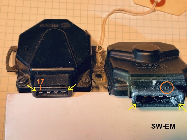
Early TPS on left, late on right. Notice the
connector orientation features
as well as Terminal 17
have swapped locations between the two!
----------
D-Jet Throttle Position Switch Suggested Maintenance:
Notes: Repeated use of the words gentle and careful here is not by mistake, and contact treatment Deoxit D5 provides several benefits to the switch connections within the TPS: Cleaning, Lubrication and Protection from corrosion.
This procedure has been put together with the utmost care, and I absolutely stand by it having successfully performed it on my own and other vehicles, with excellent short-term and long-term results, but must be used by other individuals in conjunction with normal, cautious shop practice! I cannot be responsible for all your actions, especially those which cause damage or injury. Work Safely and Carefully!
This procedure is performed with Ignition OFF.
CAUTION: Once inside TPS, do not bend, reposition or otherwise damage sliding or closing contacts in ANY way! The internals are precision components and contacts and will be easily damaged if not working exceedingly carefully!
Remove cover: Two types were fitted. Cover for early style TPS is secured by four corner screws, which can simply be removed to allow lifting off Cover. Later style TPS has a snap-on Cover (remove by gently applying prying force by hand only, to the two holding tabs between metal Base and plastic Cover on the left side, no tools are necessary(!). When these release, lift Cover from the right side tabs! Tip: Only remove Cover from later style TPS when warm, to prevent fracturing brittle cold plastic!!

Old style TPSs on the left, new style on the right. Terminal locations are
different! See also:
TPS Terminal Locations above!
Clean (internal) Comb Contacts: Once cover is removed, clean circuit board contacts with a cotton swab saturated with a few drops of Deoxit D5, move throttle to allow access to all areas of Comb conductors. No cleaning of comb wiping contact is necessary (its wiping action makes it self-cleaning!). Use NOTHING more abrasive on the conductors!...the material you remove with such actions will make it that much sooner the Printed Circuit Board (PCB) must be replaced! The goal of this procedure is not only to clean and service TPS contacts, but also push the need for replacement as far into the future as possible! Leave no arrant threads of cotton behind and inspect the cotton swab when cleaning, and repeat until it removes no further dirt.


Cotton swab saturated with alcohol or Deoxit liberates lots of surface dirt on
both early or late TPSs...
Clean (external) Connector Contacts: Remove the connector and flush any dirt or contamination from the female pins of the connector by spraying with Deoxit (use Snoozle!). Catch overspray or drippage in a rag.
Cleaning (internal) Closing Contacts or "Drag Switches":


Clean Closing Contacts (early style Sw) , saturate the corner of a
piece of standard clean office paper with Deoxit
[a single drop will do!], and run the paper (it is only
very slightly abrasive)
between both closing contacts (Green) several times
(use extreme care not to deform or relocate these contacts in any
way!). Notice slight darkening of paper where dirt has been removed (Yellow).


Cleaning and lubing Drag Switches on a late (...039) TPS. Withdrawing a
nice clean paper strip indicates a nice and clean contact ready again for service!
Final Flush: When cleaning is complete, sweep Throttle through its complete operating range several times, and generally flush and lubricate the areas which have been previously cleaned, with a flushing application from the spray can. Catch any overspray or drippage in a rag.
Replace cover, by positioning the screw-retained Cover and installing retaining Screws, or positioning snap-on Cover and gently pushing into place until the snaps latch.
Repeat this procedure for maximum protection and effectiveness, and longevity as a periodic maintenance every year, or 12-15kmiles.
---------------
My answer to an e-mail question about the difference in early to late Comb Contact design:
"Early (radial) vs late (angled to the Radius) is strictly an improvement in terms of wear. As the Slider approaches the contact at 90 Deg [in the ealier design], it is an abrupt transition and approach onto the PCB conductor...with conductor at an angle to the Radius [as found in the later design], mechanical transition of slider onto conductor would be a less abrupt/more gradual, angled transition resulting in less/slower wear. The analogy I suggest is driving straight onto a curb, vs driving onto the curb at an angle...
...that all having been said, electrically and functionally, early and later TPS version are absolutely the same, so I cannot buy the suggestion that either is more or less linked to [Miss at Cruise] MaCs, as I can attribute (or imagine hypothetically) no difference in function which could explain a difference. Wear of the throttle shaft, and adjustment, including possibly false air causing a lean condition are more likely causes..."
---------------
Throttle Position Sensing Switch

In exercising the search function, detailed info on the TPS is sparse, and in
the case of this publication, even highly imaginative...and incorrect, and
not elementary my dear Watson! It is simply not possible for the
sliding contact or alternate comb contacts to
"begin to arc as the throttle is held at
a steady position"...resistive voltage divider networks for T904, T905
(Throttle Flip-Flop, see
Throttle Position Switch Detail
above) limit current and voltage to a miniscule level which would never
be able to produce an arc! Lack of lubrication between the board
conductors and never-ending motion of the sliding contact can cause wear (this
is where the correct lubrication comes in)
[and inevitably occurring wear has even
been anticipated, accommodated, and IGNORED(!!) by superb electronic design,
thanks to Bosch! See:
The Edge Triggered Flip-Flop
above], but no arcing or carbonization
ever takes place!
[If Mr. Watson were to ever utter that advice and wisdom in my shop, he'd be asked to put down his adult beverage, and leave!]
------------------------------------------------------
External material sources are attributed. Otherwise, this article is Copyright © 2024. Ronald Kwas. The terms Volvo, Bosch and Deoxit are used for reference only. I have no affiliation with any of these companies other than to keep their products working for me, help other enthusiasts do the same, and also present my highly opinionated results of the use of their products here. The information presented comes from my own experience and carefully considered opinion, and can be used (or not!), or ridiculed and laughed at, or worshipped, at the readers discretion. As with any recipe, your results may vary, and you are, and will always be, in charge of your own knuckles, and future!
You are welcome to use the information here in good health, and for your own non-commercial purposes, but if you reprint or otherwise republish this article, you must give credit to the author or link back to the Sw-Em site as the source. If you don’t, you’re just a lazy, scum sucking plagiarist, and the Boston Globe wants you! As always, if you can supply corrections, or additional objective information or experience, I will always consider it, and consider working it into the next revision of this article...along with likely the unique metaphor and probably (likely) wise-a** comment.
