
Picture of a B20 with both pivot and bracket holes.
ALTERNATOR UPGRADE KIT, ADDITIONAL INFO
First posted 6/2005 R. Kwas, additions on-going,
Comments
added in Yellow.
Information for the well-informed installer of the SW-EM Alternator Upgrade Kit!
Included are also some practical experiences and feedbacks by installers.
-------------------------------------------------------------------------
Generator and Alternator Mounting Provisions on B18 and B20s
Special Applications
$40 Alternator Experience
Failure
of (modified) Alternator Housing
...just install a
"One-Wire Alternator"!
Another Alternator Victim of
Butchery
Minor
Installation Error
Installing a 100A Alternator
Another $40 Alternator
Experience
Alternator Thermal Considerations
Alternator "R" Terminal
Delco Alt on OE Cast Bosch Pivot
One spacer washer fits between Alt Pivot
Boss and Bracket, two don't
Broken
OE Alternator Pivot Bolt
Locking the Alternator Pivot
Failed Non-SW-EM Alternator
Bracket
Alt Kit
Bracket Interference with FI Manifold Support Arm (and remedy)
Result of loose Alternator
Loose Fanbelt
Tensioning Bar Threads in Cylinder Head
Alternator Output Rating
Discussion (reposted from FB)
Squealing Fanbelt
Remote Voltage Sensing Installation Variation
Alt Kit not as shown in Alt
Kit Description Page
Stealth Alternator Installation!
Turnbuckle Fanbelt Tensioner
Overstrong Alternator Bracket
SW-EM Alt Kit in a 164?
Reference Info:
Wire gauge AWG to mm2 chart
Links not on this page:
Alt Kit Pivot bolt with a
"Drunken Thread"!
Failed SW-EM
Alternator Kits
Alternator
Installation Failure Report and Analysis
-----------------------------------------------------------------------
Generator and Alternator Mounting Provisions on B18 and B20s:
All
B18 blocks had the three holes (Yellow)
for securing Generator Bracket.
Late B18s and all B20s added the (Green) Pivot for OE (Bosch and Motorola)
Alternators. This OE pivot is NOT suitable for mounting a Delco Alternator
because of differences in the Alternator cases (see also Special Applications
below).
Picture of a B20 with both pivot and bracket holes.
See also: Broken OE Alternator Pivot Bolt
-----------------------------------------------------------------------
Mounting an o.e. Bosch alternator using the SwEm Kit bracket. This situation has occurred twice - first, when the threaded mounting boss of a B20 block broke off (?), the bracket saved the day because it is secured to the block by the three threaded holes which were used on B18 block castings to mount the generator bracket, and fortunately were retained on B20 castings (although unused); and second , when a new Bosch alternator and (mechanical) regulator were already on hand, and didn't need to be purchased. Since no mods to bracket were necessary in this case, the option still remains for a future upgrade to a higher output D-R alt. with internal solid state regulator.
The following mechanical differences between D-R and Bosch alternators exist:
1. The Mounting boss
nominal length of the alt. castings. Bosch is shorter. See Pictures 1
and 2. Solution: Use a spacer (or a stack of washers), sized to take
up remaining space, but this spacer must be sized after cutting (Bosch) casting to
correct for belt plane offset - See
highlight on pic No.1 - once bolt is torqued, everything is locked from movement.
2. The Pivot bolt sizes. Bosch used a larger bolt than upgrade kit,
so pivot hole in casting is larger. When using smaller bolt from upgrade
kit, this could cause misalignment. See
Picture 3. Solution: Use metal tubing or strategically sized and
formed piece of sheetmetal to center pivot bolt in larger hole of Bosch alt., again, once bolt
is torqued, everything is locked from movement.
3. Belt Plane.
Different offset of alt cases. Solution: To make offset equal to
that of D-R alt., and assure pulley alignment, cut away 3/8" of casting as
highlighted in Picture 1.

Picture 1, Delco-Remy Alt. on left, Bosch on
right. Offset in mounting boss of Bosch casting which causes pulley misalignment
is highlighted.

Picture 2, Showing mounting differences
from another angle (Bosch alt. on top). Pivot boss length
differences are visible.

Picture 3, Showing mounting differences in
castings and pivot bolt holes.
----------------------------------------------------------------------------------------------------------
posted by
timbert ![]() on Wed, Dec 11th 2002 at 7:47 PM
on Wed, Dec 11th 2002 at 7:47 PM
I switched over to an alternator on my '66 122 - using the fabulous
SWEM kit
- several months ago.
[WOW...Thanks!] The one piece of advise that I didn't heed was to not buy
the cheapest AC Delco type alternator I could find ... I bought one for $45 at
the local auto parts super store. Everything seem to work okay for a couple
months. For a while now, the alternator has been making quite a racket & the
alternator pulley/fan looks to be wobbly - but everything seemed to still work &
it has been awfully cold & wet & dark to be swapping out the alternator, so I
just let it slide.
Today, when driving home at night - in a cold rain with wipers & fan going, the
headlights seemed quite dim & then, when I switched into overdrive, the radio
cut out momentarily. The amp light, however, never came on.
As I understand it, the amp light will light up if there is a difference between
the voltage produced by the alternator and the voltage of the battery charge.
So, my WAG (Wild Ass Guess) is that the alternator is not producing enough
amperage which caused the problems I experienced tonight.
Am I understanding the situation somewhat correctly? Are excessive noise & low
output consistent symptoms of a faulty alternator ?
I realize that this is probably overly simple question, but I am trying to learn
as best I can how to keep this thing going.
thanks for the continuing education
timbert
-------------------------------------------------------------------------------
posted by
Ron Kwas ![]() on Thu, Dec 12th 2002 at 8:26 AM
(amended and corrected)
on Thu, Dec 12th 2002 at 8:26 AM
(amended and corrected)
Timbert;
That is totally typical of the $40 "rebuilt specials". If the alt was making
serious mechanical noises that soon, it probably means that it didn't get new
bearings when they "rebuilt" it...I wonder what else it didn't get...that's why
I recommend paying for and installing the official AC Delco rebuilt ones...but
it's your call of course.
As to the symptoms, dim lights indicate the alt is probably not putting out
(loose belts and/or wires or that sort of thing notwithstanding), and the fact
that the AMP light did not come on is somewhat unusual, but not impossible.
There are some failure modes which do not result in AMP Indicator coming
on...especially if you installed a "unknown" alt.
In the OE gen setup the AMP lite is connected as you state...but after the
upgrade it is slightly different...then the AMP lite supplies the field power to
start the alt generating power...after that, it "self-excites", so it could be
putting out enough voltage to keep the AMP lite OFF, put NOT really putting out
power.
Have you performed the "full field test" as described in the instruction? This
bypasses the regulator and applies full field...if it doesn't put out then (indicated
by system voltage rise - connect Voltmeter to monitor system voltage) that confirms alt is for s**t
(which we kinda knew already anyway).
...bottom line is: Remove alt, take to a competent automotive electrical place, have them check
electrically, replace BOTH bearings and repair...in other words: Really Rebuild!
OR, check paperwork I sent you with kit and buy the recommended alt.
Live and learn...pay me now or pay me later...I told you so...close cover before
striking... etc...etc...etc
Cheers
... thanks for the kind words!
See also: Another $40 Alternator Experience below.
----------------------------------------------------------------------------------------------------------
Failure of (modified) Alternator Housing added 7/2010
A simple solution is often the best solution, and simple should always be the goal, but beware of oversimplification! Often, cutting away of part of the housing pivot is recommended as a simple way to allow an alternator to be used with the existing generator bracket. Maybe some owners have had success with this, and their installation hasn’t failed (yet), but the fact is that removing part of the structure of the alt pivot is BAAAAD, it weakens the housing and cuts into the structural safety margin of the entire mounting system…if this is further combined with a mounting which allows any kind of movement or vibration, you can be fairly certain that the combination will let you down at some point!...and having cut the housing to fit it, surely killed any warrantee which you might need to exercise in the future. Think twice before going the Quick & Dirty and oversimplified route…that’s really not why we drive these cars!
Shown below is a classic example of a failed Quick & Dirty alternator conversion…the (not so) clever installer simply cut away half of the pivot unceremoniously with what looks like a hacksaw, leaving a horrendous stress riser visible in the pic, (although it is also apparent that the stress riser did not cause this particular case), then used a bolt (which was likely too small in outer diameter), threaded along its entire length, including the part of the bolt which was in the pivot area. This contributed to allowing vibration which shouldn’t have occurred in the first place, to cut remnants of these threads into the pivot inner wall, before eventually leading to the fracture which broke away what was left of it. I wonder just how long (or short) of a time this installation lasted before it blew apart.
The installer who did this work should consider switching careers to one which involves a shovel!
WARNING: Picture of a major hack-job, looking at which may induce vomiting, follows:

FIGURE 4. Alternator housing, fractured at pivot which has been partially cut
away.
Also visible is evidence of vibration. Picture credits: Woodman
I warned you!

The custom designed and fabricated bracket which the SW-EM Alt Kit is based on, will allow the installation of an unmodified Delco alt with a housing unweakened by cutting. This means that the alternator housing retains its full strength, as designed, and it remains unmolested, giving the maximum strength to the mounting system, and putting the owner in a solid position for any possible future warrantee claims.
LINK to “bad workmanship” thread on British Forum http://www.volvoforums.org.uk/
http://www.volvoforums.org.uk/showthread.php?t=98883
-----------------------------------------------------------------------
"...just install a 'One-Wire' Alternator"!
[ I just had to reprint this answer to an e-mail question I received.]
A recommendation of "just install a 'one-wire' alternator" or similar is someone's quick, off the cuff, unconsidered, and incomplete advice, typically given to make the installation seem as simple as possible...
I can totally understand the appeal of this...I mean its pretty tough to screw up connecting just ONE lonely wire (not that it couldn't be done...for example, see: Screwing up one wire!)...but I have considered the details: The AMP Indicator cannot function with a one-wire installation...and there are Alt. housing variations which must be considered given the wiring and alt location right next to the exhaust in the B18/20 application...my kit has been engineered taking all these factors (and then some!), into careful consideration...and it is backed by literally thousands of successful road-miles...so if you're capable of following the explicit instructions included in the kit, and buy one of the specifically recommended, official, quality, Delco rebuilt Alts, and are capable of connecting THREE wires to the Alt., you will end up with a charging system in your vintage Volvo which has lots of electrical and mechanical operating margin, and which is therefore highly reliable...and also, an AMP Indicator which still functions, just like before!
See more here: Explanation of "One-Wire"
Reference info: Screwing up two wires (china's finest!)
-----------------------------------------------------------------------
Another Alternator Victim of Butchery...or "you can just cut half the Alt case away and bolt it to the B20...it'll be fine", and what happened a while later.
Don't do it! Just remember...the friend or "specialist" who gave that advice will not be there to help, or take responsibility, for any of the damage, when it finally flies apart!

"One-Wire" Alt (evidenced by the plastic plug at
Orange covering the Input
Connector) with fractured (actually worn-through) case. In the poorly lit
picture, it is still possible to make out the pivot which has been once again,
partially cut away at Red, and in
doing so, much of the bearing area for the mount has been lost, so as the Alt
vibrated (a secondary issue due to poor
mounting!) it eventually wore its way through the side of what was left
of the pivot. The "mechanic" who did this conversion should probably
consider changing careers to one which involves a shovel!
------------------------------------------------------------------------
Minor Installation Error: Occasionally, like when an engine is apart for a while for a rebuild, someone might forget where things go when they put it back together, and get it wrong...like this installer, who located the engine end of the Belt tensioning bar in the wrong (Red) upper hole in the head...we won't hold it against this installer (let those without sin cast the first stone!)...apparently he quickly realized the error and corrected it, by relocating the Bar securing point in the correct (Green) hole, but I thought it would be interesting to show here... Funny thing is that the adjustment slot was even long enough to allow the incorrect placement.

Belt tensioning Bar located in the incorrect upper hole
(Red) in head, when it should be
located, as before, in lower (Green)
hole.
Also visible is the pivot cast and machined into block for OE Alternators
(Yellow) and new pivot
(Orange) provided by SW-EM Kit
bracket.

Correctly mounted Delco Alternator, including Belt Tensioning Bar...
Beautiful, and ready to render reliable service for a long time!
------------------------------------------------------------------------
Excerpt from an e-mail asking about Installing a 100A Alternator:
I recommend not going above ~60A output, even with AC installed. Track record with ~60A Alts has shown continued very good reliability (zero recorded failures as a function of output current!). If you insist on putting in a higher power unit instead of one of the ones I recommend, you do this on your own...and YOU are then responsible for the engineering! The Bracket will certainly take it, but you WILL need to uprate wiring, and definitely Fuseblock...and don't come back complaining to me when your [formed sheetmetal!] Water pump pulley fatigues (from the additional possible cyclic load), blows apart, and possibly launches the Fan into the Radiator! [...because the Fanbelt had to be over-tightened to keep from squealing like a pig when it is transferring all the mechanical energy to make 100A!] I don't want to be a naysayer, but remember, when strengthening the weakest link in a chain, the next weaker link will be exposed and vulnerable...!

Fatigued WaPu Pulley, possible the result of over-tightening Fanbelt,
but there is a good chance of this happening with a 100A Alt installed!
See also: Alternator Output Rating Discussion (reposted from FB)
------------------------------------------------------------------------
Another $40 Alternator Experience:
My response to Andrew C 9/11/2016: Shredding Belts on an Alt installation:
The alternator is
working fine electrically, but it is shredding belts. I have tried 3 so far, and
have been very careful to tension them, the first 2 squealed horribly then
snapped, the last one just gave up and dropped off somewhere, and the AMP light
came on.
The angle of dangle of the pulleys relative to one another seems ok. The pinch
bolt is nice and tight, tension seemed OK and the pivot was cinched up too.
What am I doing wrong? What would cause this? My
Response in Blue: As a
rule, Belt should be in a single plane, which obviously means pulleys must also
be (it should be noted that Belts can take a LOT of misalignment
[they are fiber reinforced, but after
all, still a flexible rubber band!]...recall the
90degree turn with 90 degree axial twist of the 60s Corvair installation!), but
I suggest you check this critically with a fresh eye again!...triple holes into
block for Alt bracket are slightly oversized to allow some minor adjustment...
but this is first time I've heard of multiple belts shredding themselves, so
something is very wrong indeed! It may be an possible misalignment of
pulleys (although I fail to see how, unless something is assembled wrong, but I
can't imagine what might be either!), or that one of the driven pulleys (WaPu,
Alt) are sluggish to turn somehow (remove belt, check bearings in each for free
turning ability) and at the same time, I'd also check all pulleys for
imperfections on the belt running surface which might be damaging the belt
(although minor ones of these would normally get polished away after a short
while of running), but maybe a significant nick in pulley is insulting the belt
every time it touches it, taking a chunk out of it, leading eventually to belt
failure. More likely, a squealing belt is caused by a very high (maximum)
electrical load causing belt to slip...if allowed to persist, this will overheat
belt and can lead to failure, as it has in your case (multiple times!)...what is
State of Charge of Bat? ...have you charged Battery overnight with a line
powered Charger?...you should!...expecting Alt to recharge a completely flat
Battery (or a Battery with a shorted cell, which will continuously load the hell
out of Alt) will result in a persistent high-Alt load condition which won't be
doing the belt any favors, and can lead to these symptoms. Also, CAREFULLY
feel around (or look with an IR temp scanner) for hot spots in the elec
system...all that elec energy generated under max load condition would be going
somewhere! That's all I can think of right now... Again, if you wish
to discuss live, you're welcome to call me today at XXXXXXXXX
I am going to take the alternator off tomorrow as it will aid me in removing the
manifold, I will have another closer look at the bracket and see if the pivot
needs packing or something. Take and fwd a picture
just off the plane of the belt to allow me a look, before removing. I'd be
quite interested in knowing and understanding root cause of this issue, as it is
rare and preventative measures might need to be included on SW-EM site, or at
least in Alt instruction. Good Hunting!
The exact cause for the shredded Fanbelts was not initially fed back by this installer...as it was, he returned the Alternator to the supplier who replaced it with another...when he installed the replacement, the problem was cured! It should be noted that this WAS NOT an official Delco rebuilt unit, but one of the second source suppliers, proving once again that you usually get what you pay for!
Update: This is the feedback from this installer: "Yes, I did have shredded fan belts. The reason was a “knackered” alternator, i.e. it was almost seized. It was a very cheap rebuilt one, I should have known better.
Anyway, I got a nice AC Delco one and it has been fine ever since. It was nothing to do with your alternator mount. " All's well that ends well!
------------------------------------------------------------------------
Alternator Thermal Considerations:

Cooling air is drawn into the rear of Alt, past the electronic components, and
is discharged out the front,
by way of the centrifugal impeller.
Green (A) is a threaded hole in Alt
Housing. It can be used to connect an addition Chassis Cable, and possibly
to secure a Heat-Shield (see below). Note the direction of rotation (yellow).
I haven't had any reports of heat-damage to an Alt upgrade [MAR 2022 Correction: Limited!...an update in in the works on this!], so I don't think a Heat-Shield is necessary, but given the above, my recommendation for anyone considering adding such a shield would be to form it as shown here in yellow:

Heat-shield concept for Delco Alt installation: Heat-shield (Yellow) would
block warmer air plus radiation from Headpipe from rear of Alt while
directing cooler air (Blue) from the front of
Alt into the Cooling Air Intakes.
It could (and must be!) WELL secured by single fastener into threaded hole in Alt
case (Green A).
It would be highly advisable to also use two additional securing points
(Green B) at the
Alt housing bolts).
Note: All advantages would be quickly negated if your groovy Heat-shield were to loosen and short the Alt output stud to chassis!
Link to Brickboard Thread: Alternator Heat Shield: https://www.brickboard.com/RWD/volvo/1641961/120-130/alternator_heat_shield.html
While on the subject of Heat Shield and Cooling Air flow, here is a reference picture of a Delco Alt installation with an IPD header. The hot exhaust is not too far away, but there's plenty of Cooling Air available given the general direction of the airstream and the hurricane of turbulent airflow occurring under the hood!

------------------------------------------------------------------------
From FB thread about installing a Tach originally for a diesel powered vehicle with a W terminal on Alt ("R" terminal on Delco Alts):
I agree that a Tach originally meant for a diesel (which has no Ignition System from which to take an RPM related signal) cannot be directly used to monitor RPMs on a gasoline powered engine, but understanding how it does work on the diesel, and a bit of engineering, allows using it on a B18/20!
Calibration: The only question in operating a former Diesel Tach in a different Alt would be the relationship of the frequency at the W ("R") terminal at a given RPM, on the original engine, versus the frequency from another Alt, and this would clearly be a function of the pulley diameter of the original Alt which the Tach played with vs. pulley Dia of the Delco.

From those Links: http://www.thesamba.com/vw/forum/album_page.php?pic_id=329870

http://www.rangerovers.net/rrupgrades/electrical/delcoclassic.html

...and if the Alt does not have a W terminal (R for Relay on Delcos
[don't ask
me why!] cast into Housing), it can simply be added to one of the output phases
as seen above! Note that the "Bat" terminal (2) should more correctly be
named: Sense, to avoid confusion with Battery (output) terminal.
Taking the Tach signal from the Alt also reminds one of early mechanical Tach drives, which would be taken by a speedometer-like cable drive from the Generator.
Reference Link to thesamba thread: European alternator “W” wire question 1.9 AAZ https://www.thesamba.com/vw/forum/viewtopic.php?t=746516&highlight=
------------------------------------------------------------------------
Links:
Alt Kit Pivot bolt with a "Drunken Thread"!
Discussion on Swedespeed Forum: "New 1800E owner, longtime Volvo owner - question about alternator options" https://forums.swedespeed.com/showthread.php?607833-New-1800E-owner-longtime-Volvo-owner-question-about-alternator-options
----------
Thread about installing a SW-EM Alt Kit: http://forums.turbobricks.com/archive/index.php/t-274372.html
My posting to that thread
Forum;
I realize this is an ancient thread, but I ran across it again while doing some
research and wanted to chime in with a couple of stupid comments. First, a big
THANKS all who recommended the engineered Sw-Em alt kit!
Advice often seen: "simply install a "One-Wire" Alternator..." that's
oversimplified advice (it comes from people working on tractors, who apparently
have trouble when working with more than ONE wire!), given by those who want to
make it sound as easy as possible...what they don't mention is that when doing
that, you also loose AMP Indicator function! If you can handle following
specific detailed instructions, and connecting up all of THREE whole wires
without screwing it up, that's the preferred way...and you'll retain the
function of the AMP Indicator...just like before!
A couple of words about installing a 100A Alternator: First, a question: What
would you possibly need that much power for in your car? Add up all the Loads
(including the intermittent/occasional ones like Window lifts and Rear Window Defroggers)
and you'd probably have trouble exceeding 1200W. And if you have a 1000W
stereo installed, know that it draws less than 1/10 of that when turned up to
make your ears bleed!...the only times it truly draws 1000W is on bass peaks,
and they don't last very long (unless your showing off, in which case I probably
can't help you!). If you want to supply bass peaks for a killer stereo, install
some soup-can capacitors, and be done with it!
Also, those 100A don't come from nowhere!...they come from the engine...more
specifically, the Crankshaft, by way of the Crankpulley, Fanbelt and
(sheetmetal) [B]Water Pump Pulley[/B]...if you install a 100A Alt, in order to
transfer that much mechanical energy through one belt (without squealing like a
pig, if it's possible at all), you'll have to tighten up the Belt like that of a
high-wire act across Niagara Falls...then you may get this for free:
...so good luck!
...and I haven't even mentioned the wiring yet...remember...when strengthening one part,
the next weakest link in the chain will be the one to break! If you simply want
a reliable electrical system in your vintage Volvo, vigorous Wipers, WHITE
Headlights, and a fully charged Battery with which to get started next time, I
recommend and have engineered the kit to install a 60A Alt...then drive it like
you hate it, knowing that it will likely be as reliable as before...as thousands
of customer miles have shown!
Cheers
-----------------------------------------------------------------------
Delco Alt on OE Cast Bosch Pivot:
Alt kit inquiry from Matt Y.: (Comments added)
"... the (Delco) alternator that is currently installed on my 122 is using the cast mounting point (I call it the OE Pivot) on the B18 block. It is out of alignment by 7-10mm, the alternator bracket is at the end of its reach and interfering with the alternator body so I can’t get the belt any tighter (it squeals on start up). I’m curious if moving to one of your brackets would solve this for me and give me the clearance I need to get on a smaller belt? The alternator is limited by the coolant hose when moved inwards. I’ve attached a couple of pics for reference."Matt's pictures used with his permission.


Excerpt from my response "...the pictures...they show the misalignment (high, close to exhaust, and toward the rear, as apparent above in comparison of Alt housings), well, (at least installer didn't cut away part of the Alt housing to make it fit, see: Failure of Modified Alt Housing ) and yes the SW-EM Kit would absolutely cure all the issues (Alt position, therefore belt misalignment, adjustment range, interference) because it will relocate the alt a bit lower (as can be seen here: SW-EM Alternator mounting provisions B18 and B20 )
-----------------------------------------------------------------------
One Spacer Washer fits between Alt Pivot Boss and Bracket, two don't:
...from and Alt Kit Washer spacer issue email exchange...:
From A.D.: The alternator is loose within the bracket, but there is not enough space for two washers, so I can think of filing the mounting boss to allow for another washer or dismount the bracket and close it a bit, the play between the bracket and the alternator boss is less than 1 mm, but is enough to have it wiggle when the pivot bolt is fully tightened.
Response: There is typically only room for installing one washer on a nominally sized [2 inch] alternator pivot boss, so its not a problem if there is not enough room for two washers. The remaining gap will be closed when tightening the pivot bolt. The intent of installing a washer is to take up excessive gap.
A.D.: Unfortunately, the gap does not close after tightening, I guess that the remedy left is to put two washers, which will require a bit of filing on the alternator boss. I have been following the Tech bulletin to the letter.
Response: Again, the washer(s) are only present to take up excessive space...that's it!...if one washer fits, but not two, you could simply pry apart the bracket slightly (if possible...I realize the bracket is quite beefy and may not allow this)...or as you suggest, file the mounting boss slightly to make room for the second washer, or even cut another thinner spacer washer, or two, from a thin piece of sheetmetal (like even a soda can) and use that...I realize that coming from the aerospace world, you have been trained to follow instructions to the letter (and that is certainly good!!), as instructions have been authored by highly qualified individuals after much consideration (as have mine!), but in this instance, it's just not critical, and you may make a "judgement call" (you may not have an Airframe and Powerplant (A&P) rating, but in this case, its allowed!)...the important thing in the end when all hardware is fastened to final torque, that Alt is ONE with bracket, and bracket is ONE with engine, in both cases meaning that NO relative motion is possible. [See below!]
A.D.: I filed a bit the alternator boss, added one washer and problem solved.
Response: Great!
Reference:

Mechanical conditions between Alternator Pivot Boss and SW-EM Bracket.
-----------------------------------------------------------------------
Broken OE Alternator Pivot Bolt: [This is not a failure of the SW-EM conversion, but of the OE arrangement with Bosch Alt, and demonstrates once again how important proper mounting of an(y) Alt is.]
A failed OE Bosch Alt mounting occurred, due to looseness of pivot bolt allowing vibration and failure of the (1/2"!!) pivot bolt.
[As I have noted before, the OE design is an "Overhanging Load" (or "Cantilevered Mass" ), as mass of the OE Alt is supported ONLY on one side of the Alt housing pivot. This is quite OK when everything is nominal and tight and no movement is possible. If however the pivot bolt were to loosen for any reason (or not be properly tight in the first place), the system and mount would be subjected to horrendous forces generated in the overhanging mass mode, on mount and pivot bolt, the vibration input, and plenty of it(!), being transferred by the Fanbelt, and in this case sufficient to eventually fatigue and break the beefy 1/2" pivot bolt!!
Alternately, I have also heard of the mount on the engine block also break off (no picture, sorry)!! This is much less so the case in designs where support is provided on BOTH sides of the pivot, as with the SW-EM design bracket. A double sided support design is therefore somewhat less susceptible to catastrophic failure, AND also much more failure-tolerant if one were to occur!]
Where loose Delco Alts have caused failures, this shows that a loose OE Bosch can suffer under the same situation!
Failed OE Bosch Alt mounting due to looseness of pivot bolt allowing vibration and failure of (1/2"!!) pivot bolt. Note Galling, a sure indication that Alt was vibrating and not securely fastened!

Aftermath of a loose Bosch Alternator! Even a 1/2" Bolt is no match for
cyclic fatigue!
Picture by Vaughn H. and used with his kind permission.
Link to Thread https://forums.swedespeed.com/showthread.php?596513-Gosh-All-Fishhooks!&p=7293589#post7293589
In the picture, circumferential galling is the unmistakable evidence of long-term vibration between two surfaces, and scarring at 4-7 O'Clock likely occurred just after final separation, when jagged edges of bolt vibrated against pivot.
My comments to thread:
"Such a failure is a rare occurrence, but not one which hasn't happened
before...and galling apparent on the pivot from 1-4 O'Clock is clear evidence
that pivot bolt or Fanbelt tensioning bar, or both were loose, allowing movement
of the Alt, causing cyclic forces on bolt which caused breakage...there is
certainly plenty of vibration input from the belt! Alternator should be checked
to be absolutely secured to block and not being able to move in any axis...good
practice is to check for secureness of Alt (and tightness of Fanbelt) any time
hood is opened for fluid checking or other service. I would wager that the
On the Alt conversion brackets which I offer, the ONLY failures which have
occurred on Alt housing, or bracket or pivot bolt, have occurred for the same
reason: Looseness, and the fact that there was relative movement between Alt
case and bracket, or bracket and block! If Pivot bolt is properly torqued, after
the Fanbelt has been tensioned, Alt will be securely ONE with block, and will
stay that way!...but I include a nylock jamnut in my kit for additionally
locking the pivot bolt in place (belt and suspenders...a triple safety feature,
just because I can!). "
[I would bet a Hot Fudge Sundae that such a failure was caused by the pivot bolt not being tightened, AFTER fanbelt tensioning!]
-----------------------------------------------------------------------
...not to make a big deal of it, but it must be pointed out that installers have gotten it wrong, by not doing the last step (3), which resulted in mechanical failures! The Pivot must be locked after Fanbelt tensioning!
The proper technique and procedure for securing the Alt in the SW-EM conversion, is to FIRST tension Fanbelt, then, lock the Alt from pivoting (and vibrating!) by securing Pivot Bolt to final Torque. The Torque required can, and should simply be checked before BEFORE tensioning Fanbelt, by tightening Pivot Bolt until it locks Alt from pivoting...and it should be able to lock the Alt in-place by approx 30-35Ft/Lbs, certainly needing no more than 40Ft/Lbs!
A Torque Gauge is not absolutely necessary for this, but if the Torque required to lock Alt from pivoting seems extraordinarily high, the situation of an undersized Alt Pivot and excessive play between Alt Pivot and Bracket Wings may be occurring, so the Spacing Washer supplied with the kit may be necessary to close the gap (see: ...Spacer Washer above!).
CRITICAL TIP to Installers: Installer is NOT done when the Fanbelt Tension has been set, and its securing Bolt tightened! The Alt Pivot Bolt MUST be torqued and Alt Locked in Place after that also!
1. Preperation: Test tighten Pivot Bolt to assure it will lock Alt from pivoting (if necessary, install spacer Washers supplied with Kit!). Loosen Pivot Bolt again, to allow Alt to pivot, in preparation for Step 2.
2. Tighten Fanbelt by pivoting Alt Housing. A lever between Engine and Alt can help. Tighten Bolt which secures Fanbelt Tensioning Bar to Threaded Adjustment Lug of Alt Housing. Do not overtension Fanbelt!
3. Lock the Alt from pivoting (or vibrating in service!) in Bracket Pivot by tightening Socket Head Pivot Bolt. Use 5/16" Hex Wrench. I installer is not certain Alt is locked from pivoting, simply loosen the bolt securing the Fanbelt Tensioning Bar in Step 2...Alt should not pivot, loosening the Fanbelt...if it does, pivot was not adequately fastened! Go back to Step 1! If Alt does not pivot when loosening bolt securing the Fanbelt Tensioning Bar, pivot Bolt is adequately tight to lock Alt in place, and bolt securing the Fanbelt Tensioning Bar can be retightened, and installation can proceed to Step 4.
4. Finally, Tighten the (optional) Secondary Locking Jamnut (Nylock) to lock the Pivot Bolt in place.
-----------------------------------------------------------------------
Failed Non-SW-EM Alternator Bracket:
Occasionally, someone will make their own bracket to fit a Delco Alt onto a B18/20 engine. The one below actually looks decent, but without the lower hole on the base, supporting the structure against torquing from Belt tension variations with vibration, and from the unmistakable evidence of galling left at the pivot holes, it clear that the Alt was doing a little dance (NO, a lot of dancing!) which finally lead to a fatigue failure of both pivot tabs. Allowing MOVEMENT of the Alt is what causes things to fatigue and break! This broken non-SW-EM bracket has now been replaced by an official SW-EM bracket with that third hole for stability!
Austen B. picture, used with his kind permission.

-----------------------------------------------------------------------
Alt Kit Bracket Interference with FI Manifold Support Arm.
When installing the SW-EM Alt Kit on FI vehicles, it has been observed that the Support Arm for the Intake Manifold will interfere slightly with rear of alternator bracket. D. Waterman remedied this by trimming 5/16" from the left side of bracket as shown below. This adjustment results in clearance to the Support Arm, and allows the bracket to mount in place normally and without further problems. This modification of bracket does not affect the overall mounting system or strength. David Waterman pictures used with his kind permission.


SW-EM alternator bracket on a fuel injected engine. Interference with
Manifold Support Arm is apparent at BLUE.


Detail of SW-EM alternator bracket area which needs to be trimmed/removed when installing on an FI
equipped engine.
-----------------------------------------------------------------------
Result of loose Alternator (mounted on SW Alt Kit bracket):
There is plenty of Vibration being transferred to the Alt by the Fanbelt any time engine is running. The Alt must be absolutely solidly mounted to not be able to dance to this tune!
Below is what results when the Alt is not solidly one with the SW-EM bracket, this MUST BE CHECKED FOR at assembly, and must not be allowed! Often, a loose condition does reveal itself, even if it develops sometime later, as will be associated with vibration or rattling noises. Note that often, because of the variable nature of resonant conditions occurring due to variable conditions, these vibrations are more pronounced or only occur at certain RPMs. Friendly warning: If you don't take note of the associated noises, or take note of them and "just turn the radio up", eventually things will break!
Tip: Listen for "new noises" and investigate them! Luckily, Dennis N. caught the condition shown below, before it completely let go, but from the amount to wear evident in the Alt pivot, it was well on its way to that. [He must have really had the tunes "turned up"]
He sorted it by replacing separated Motor Mounts, by replacing the worn Alt housing, and by checking for solid mounting on reassembly.

Result of an Alt, loose on the SW-EM bracket!
Displacement is approaching being
equal to the pivot bolt diameter!!
Dennis Needham picture posted with permission.
-----------------------------------------------------------------------
Loose Fanbelt Tensioning Bar Threads in Cylinder Head:
The OE Fanbelt Tensioning Bar is reused when installing the SW-EM Alt kit. It is important for keeping tension of Fanbelt at the adjusted level, and it is subjected to much the same vibrations Fanbelt is imparting to rest of the Alt mounting system. The securing bolt on one of my Alt installations has twice backed out and been completely missing(!), and noticed at the next under-hood inspection. I have also had feedback of this occurring on two customer cars. Thankfully, I discovered this on my own car when investigating "new noises", and before any secondary damage resulted.
Maybe the threads in Cyl Head were loose or sloppy, [I know the bolt was properly tightened!] maybe conditions were just optimum for this loosening to occur, but it certainly must be permanently prevented! This could be simply done by applying a thread-locking compound...but that is not immediately visible and inspectable...my solution was to drill and safety-wire the bolt. A safety-wire is positive, obvious and clearly visible! Ref: https://en.wikipedia.org/wiki/Safety_wire

Delco Alt Installation on SW-EM Kit bracket showing 1/2" "S" bend deviation from
straight shown in Yellow,
required in Fanbelt Tensioning Bar to allow good alignment with threaded boss on
Alt Housing.
Richard G. fedback another solution, which I find possibly susceptible for the reason given below...
Richard G. picture posted with his kind permission.

Richard's Fanbelt Tensioning Bar was one of the thicker styles fitted, so
instead of trying to make the "S" bend, he spaced the Cyl Head mounting surface
out with a stack of washers (he
also retained the dual rubber shock-mount) . I warned him this could
exacerbate the self-loosening of the bolt.
Excerpt of my e-mail exchange with Richard:
"Spaced out like that, you clearly
don't need the "S" bend, but beware, I have had two reports of that
securing bolt into the Cyl Head loosening, and I have personally experienced
this also, finding the bolt missing completely (twice!) when investigating the
accompanying (new) noise(s)...I believe the spacer solution would likely exacerbate the
possibility of this happening, because of the "overhanging mass" of the bolt and
so many washers, so I advise at the very least, to keep an eye on it!
After loosing the second bolt, I figured the threaded hole in the Cyl Head was loose, or that there was a high concentration of vibration at that location...either way, a more positive help was required...I suppose a chemical threadlocker would have also been an option, but knowing these loose their effectiveness with elevated temperatures, which are certainly present at the Cyl Head, my solution was to safety-wire the replacement in place (which is also immediately inspectable!), for absolute security and peace of mind. This solution has served without failure in the long-term. "
Notice the location of Fanbelt Tightening Bar in the above pic is on the adjustment lug, and in-front-of the Alt Housing...it can just as easily be located behind the housing. [Reference this Alt installation on a B16: Fanbelt Tensioning Bar S-Bend ] It makes little difference, it's just when locating it in front of the lug, when the belt tension is adjusted such that the Alt is pivoted way out, the FTB can interfere, and slightly foul with the cooling air impeller...this needs to be watched for during installation!
-----------------------------------------------------------------------
Alternator Output Rating Discussion (reposted from FB):
This discussion is interesting and informative for anyone considering an Alt conversion, and wondering about the output rating of the Alt. The intent here is to show questions, answers, and points of discussion. Since these are screenshots (and therefore a snapshot in time), postings by individuals which might have occurred after the screenshot was made, will obviously not be shown.
For reference, 12V X 60A = 720W...and one horsepower is equivalent to 746W, so at maximum electrical output, a 60A Alt puts about 1 HP of mechanical load on the Crankshaft by way of the Fanbelt (we use the term about, because there are no inefficiencies accounted for, in this Rule-of-Thumb).
My recommendation continues to be against fitting an Alternator with rating more than ~60A, because with a Chaging System rated at this magnitude, existing mechanicals and wiring do not need major uprating. If someone's elec requirements are that they indeed need more power available, it can certainly be accommodated, but further engineering would be necessary in order to assure safety and reliability of the installation. I therefore stand by my statements and recommendation made herein, and I presume everyone else posting does also, but if anyone does not like the republishing of their names here, let me know and I'll remove it.


Link to SW-EM Electrical Ramblings shown here.
-----------------------------------------------------------------------
Squealing Fanbelt on SW-EM Alt Kit
installation after adding Fog Lights
[Excerpt of an e-mail exchange with an
installer of the Alt conversion: ]
He asks: "...never had an issue before I installed aux fog lights. It seems that I get a squeal only when I turn on the fog lights."
My response: " ...this is not too much of a surprise!
A squealing Fanbelt is due to is slipping, and since the additional electrical load of high current loads placed on the elec sys is effectively transferred to the Alt by way of the Fanbelt, it might certainly squeal when turning the ON Fog Lights! Remember, once engine is started Charging Sys supplies ALL elec requirements, from recharging the recently partially discharged Battery, to ALL elec Loads you have switched ON. [Battery supplying power while engine is running is an unusual situation and means something is wrong...from Chg Sys output being insufficient, to too many Loads being turned ON and requiring power.]
I wonder, and wouldn't be surprised if it also squealed for a few seconds after engine start even without the Fog Lights ON...the additional load is from the Battery (Starting energy having pulled SOME energy out of the Battery, partly discharging it). Don't forget Fanbelt tension is a fine dance and compromise between being loose and slipping/squealing under high load circumstances, and being unnecessarily too tight and causing Water Pump bearing wear or even worse, causing the sheetmetal WaPu Pulley to fatigue and fail and this:
Ideally, the Belt tension should be just tight enough to transfer, without slipping/squealing, the highest elec Load which occurs, and no tighter, which would cause higher wear and tear than necessary...(hence my "fine dance" comment). [...and yes, I am aware that this is the fourth(!) time this picture is being shown on this page!]
Since you have installed Fog Lights, your Fanbelt must apparently be adjusted a bit tighter!
I recommend the following (ALL with engine OFF, and NOT running!): Adjust Tension of Fanbelt just a bit tighter, and possibly inspect and deglaze pulley contact surface of Fanbelt a bit with emery cloth if it looks totally glassy, or even replace/renew the Belt.
To adjust, loosen the Tensioning Bar locking bolt on top, and also Pivot bolt (3/8" Allen) below (it does have a locking nut behind bracket which should also be slightly loosened first, access is from below!), just slightly and just enough to allow pivoting of Alt, and using a long lever between engine block and Alt housing, lever the Alt housing away from engine to tighten (BUT NOT OVER-TIGHTEN!) the Belt (yes, there is some judgment called for here!)...tighten the Belt adjustment bolt on top when at a reasonable belt tension is achieved, and also the lower Pivot bolt. Recheck tension, and if necessary retighten Pivot if any movement between Alt and Bracket, or Bracket and engine block is noted when giving the Alt a strong tug by hand! NO MOVEMENT SHOULD BE POSSIBLE AND/OR OBSERVED!
After assuring engine is safe to start, Start engine and note if any squealing occurs immediately after Start, or when turning ON Fog Lights or other high elec loads. Make adjustments as necessary...remember, Pivot bolt allows pivoting, and Bolt on tension bar locks it in place...BOTH should be loosened to allow adjustment, and MUST bet tightened to prevent ANY kind of movement, including slight, when finished. Alt MUST NOT BE ABLE TO MOVE...the Fanbelt is the ONLY thing which does any moving!!! When satisfied with Fanbelt adjustment, tighten Pivotbolt Locknut.
There is nothing wrong with learning!...everybody learned at some point...and ALL of us should strive to continue to learn! So when doing this work yourself, Work Safely!...especially around moving parts of the running engine! Also remember that the B+ terminal on the back of Alt is directly connected to Battery, so DO NOT inadvertently connect it to chassis with a metal wrench! BIG sparks would result! If necessary, to prevent such an inadvertent excitement, temporarily disconnect Battery while making Alt adjustments.
Work Safely! "
-----------------------------------------------------------------------
Remote Voltage Sensing Installation Variation
The SW-EM Alt kit harness ties the Voltage Sensing input of the Delco Alt VReg (Terminal 2), directly to Alt B+ output terminal, with a short jumper, because in the typical installation in the Volvo vehicles, the length of the wire between the Alt and vehicle Bat is less than three or four feet (of a heavy gauge cable), so the voltage drop which occurs across this minimal Resistance due to cable length and other currents flowing through this path, is quite small and can practically be ignored. This implementation is called "Local Voltage Sensing".
In vehicles where this distance is significantly longer, like a B18/20 installation in a boat, or remotely from engine compartment in a trunk, in order for the VReg to get a more accurate sense of the Battery Voltage (not the voltage some cable length/Resistance/Voltage away, which will be more influenced by other currents), the VSense can be relocated from the Alt B+ terminal, right to the +Battery Clamp with a separate 14ga wire, as shown below.
Again, "Remote Voltage Sensing" is not necessary in the typical Volvo installation, but I thought I would show and explain the difference.

In this excerpt of SW-EM Alt Kit Installation Diagram, the normal Red wire
used for Local V Sensing is
removed,
and replaced with the
Orange connection from
Alt Sens (Term 2) to Battery + terminal, to implement Remote V sensing.
See also: http://www.sw-em.com/gm_charging_sys.htm
-----------------------------------------------------------------------
Alt Kit not as shown in Alt Kit Description Page:
An eagle eyed Chuck S. noticed when he received his Alt Kit, that the Pivot Bolt was different than that shown on the Alt Kit Description Page.

Excerpt from the Alt kit picture in question.
He writes: "Your website examples show the bracket using a hex head bolt.
It is not the black metal [black oxide
finish of the H-K pivot bolt] of the strongest metal available.
Also, the bolt is short...it does not include the nylon lock nut."
My response: "Chuck;
Good eye! The pictures on the site indeed show the Alt secured with a
standard Hex bolt and no locking nut. These are early pictures before I
specified the better [superior!] H-K pivot bolt,
plus Nylock securing nut. As a point of information, it was never fed back to
me that the earlier configuration bolt had failed, or was not good enough in any
way, but by changing to the better, longer H-K bolt, and adding the Nylock nut,
my intent was to add even more safety margin, with a goal of ZERO failures! As
it was, there have been several failures, one even of the H-K bolt, but in
ABSOLUTELY EVERY CASE, the failures were directly traceable back to improper
(loose!) mounting! See also:
https://www.sw-em.com/Failed%20Sw-Em%20Alternator%20Kits.htm
The kit has been engineered with good practices, lots of margin, and it comes with the knowledge, and actual field experience, that others with installations just like it, have literally THOUSANDS of trouble-free miles behind them, when it was installed per the recommendations, but in the end, particularly if they deviate from recommendations, it goes without saying that the installer is always responsible for the installation in the long-run... "
-----------------------------------------------------------------------
Stealth Alternator Installation!:
Australian John Johnson pictures from Faceplant![]() ,
Volvo Amazon subpage (pictures are actually of an 1800), used with his kind
permission.
,
Volvo Amazon subpage (pictures are actually of an 1800), used with his kind
permission.
John clearly likes his chrome, but also an otherwise original (looking) configuration, even though he has an Alternator installed (actually, he notes, it is a Generator housing internally modified into an Alternator, so a real "Stealth Alternator Installation", and not a SW-EM Alt Kit! I have requested details on this!). Although the wiring is functionally consistent with the SW-EM conversion, his implementation is clearly an expert level modification which would take longer to implement!

A peek into the shiny VReg shows the original internals have been completely removed and replaced with a simple soldered jumper, which directly connects what was the Generator (now Alt!) Output, D+ terminal, to the Battery, B+ terminal, effectively bypassing the former Cut-out Contact, which is of course, no longer necessary with an Alt.

Excerpt from 122 Wiring Diagram (Color codes for the 1800 added in Turquoise!), showing Charging System, and associated, also wiring changes which allow a gutted and modified VReg (Charging Control) to stay in place for an original appearance, after an Alt conversion has been performed. Even the original sleeved three wire harness (Blue), between VReg and former Gen, can be repurposed and reused. Red highlighted area, wiring and connections are IN. Yellow highlighted area, wiring and connections are OUT.
Note that wire jumper inside VReg is carrying the Alt output current, so must have a similar heavy wire gauge as the other conductors in the path: (6mm2) 10AWG. See Reference Info below.
Note also that the VSensing (Terminal 2) of the Alt Connector is again directly connected to the B+ output terminal for Local Voltage Sensing.

-----------------------------------------------------------------------
Unusual Alternator installation, using dual-groove Crankpulley: By apparently using the cast-in pivot of the B20, with a Delco Alt, a previous owner/installer was able to (at least partially) compensate for the pulley offset, by using a dual-groove Crankpulley and two separate Belts. [Current owner has not gotten back to me with additional details...I'd love to see a detail of the pivot and mount!]
Nathan Courtright FB picture, permission requested (he said he would get more, better pix):

One Fanbelt for Waterpump, one Fanbelt for Alt...hmmm!
Excerpt of my exchange with new owner:
"In studying your pic further, I see what's happening...and it's pretty interesting, as it is quite unusual!! ...someone has used the outer groove of a double Crankpulley to run just the Alt mounted on OE Alt pivot of engine. They have not done the typical hacking away of the Alt housing to give alignment (good!), however, since the 1/2" pivot bolt must be used in the block, the hole in the Delco Alt had to be enlarged (less than good!), and a separate Fanbelt had to be fitted, only driving the Alt. There still appears to exist some misalignment, so I expect accelerated Fanbelt wear on that one to some extent.
...so what you are trying to do by fitting a double groove WaPu Pulley would allow you to run a single belt, however, it would not address the misalignment still present. Some more pix would still be good...including one showing plane of Belt.
[And now that I think about it some more, I must ask: How is the WaPu Belt tension adjusted?...this is normally done by varying the Alt position, but with separate Belts, now there is no provision for it??]
This is a definite candidate for my "Special Engineering by a PO Page"!
----------------------------------
Picture of a Alt installed on the Distributor side...it's not on a SW-EM Alt Kit, but I though I would show it here as it is a nice solution...

Distributor side (Bosch) Alt Mount with Turnbuckle Belt Tensioner...also
applicable to the Manifold side mount Delco conversion! Permission
requested.
My response to
![]() posters, most
of whom did not like this arrangement, suggesting it was not up to the job.
posters, most
of whom did not like this arrangement, suggesting it was not up to the job.
" Contrary to some posters who think its not strong enough...I like it, and
I'm even looking at adding such a feature option to my Alt Kit, because it
allows precise and less rustic setting of the Fanbelt tension...no more levering
between the Alt and engine with a tire-iron or big screwdriver!
To those who don't think it will be strong enough, I remind them that this link
only locates the top of Alt for the purpose of setting Fanbelt tension...and
AFTER Fanbelt tension has been set, the Pivot below should be tightened and
locked to hold the entire mass of Alt in place...point of fact, this link could
be removed after pivot is locked (not that this is recommended, but strictly
looking at this from a standpoint of mechanical analysis!)...Alt mass is NOT
supported by this link normally...only IF the pivot loosens or is not tight for
other reasons! That's why link should obviously be present and its locking nuts snugged...it is a BACK-UP, but not the primary securing feature! "
----------------------------------
Overstrong Alternator Bracket:
Example of a possibly "Overstrong" home-made Alt mount to fit the Delco! By making the bracket of what looks like 3/8" stock, and not leaving much, if ANY flex in the front pedestal, this will set up a situation of little, or insufficient flex to clamp the pivot securely in-place, to keep it from vibrating(!), and this is a crucially important requirement of a properly designed and constructed mount. The front support of the SW-EM Bracket actually is intended to flex slightly and close the clearance to Alt pivot to zero as the pivot bolt is tightened.
The bracket is a similar design to the SW-EM Delco-to-B18/20 bracket...with the downside that it does not make use of the front fastening hole into the engine (leading possibly, to increased vibration), and with no flex provision for locking the Alt in place after Fanbelt tightening (inability to lock the Alt into the pivot is THE reason for pivot bolt or mount failures). These negatives would need to be carefully compensated for at time of installation...
When using a bracket design like this, shimming the Alt pivot to absolutely minimize clearance, and verifying it is completely captured and locked, after Pivot Bolt is tightened, is crucial!
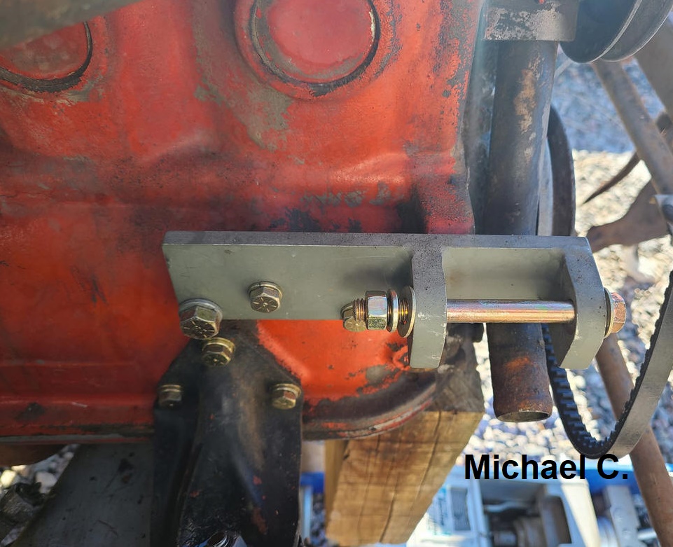
Source: Michael Cook
![]() posting from
Nov 2021.
posting from
Nov 2021.
----------------------------------
A 164 owner has inquired about the Delco conversion on his B30 equipped car...he noted it currently has a 35A Bosch Alt installed(?), with AC...so it sounded to me like this installation has already been downgraded from a 55A, which I believe was installed as standard equipment from the factory, when an AC was present.
it was time to look at the possibilities here...naturally, the first option would be to (re)install an OE 55A Bosch Alt, but prices for these units are north of $400, so he wanted to at least compare what the costs of a SW-EM Delco conversion might be...the critical factor, and possible showstopper being if the original 3 holes for the Generator mount were present on the B30 Block...and since the B30 was never outfitted with a Generator (to my knowledge), I asked for a picture. Shown below, it is immediately clear that since the 160s always came equipped with an OE Alt, and only had the cast-in pivot.
So the bottom line is, without further engineering and modifications to the block or Delco Alt housing to assure Fanbelt alignment, it is NOT POSSIBLE to simply install the SW-EM Alt kit onto a B30...desirable as it might seem to be from a cost standpoint...sorry!
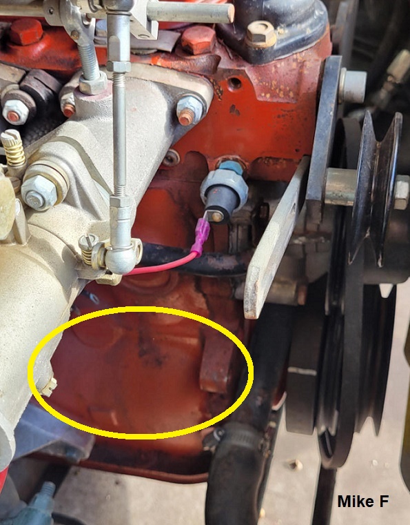
Look ma, no Gen mount!
B30 area of interest, with Alt removed...this engine only has the cast in pivot for the OE Alt...it does not
have the necessary three hole cast-in mounting bosses necessary for a SW-EM Alt
bracket! Picture by Mike Fitzgerald, and posted with his kind permission.
I also spy a non-stock intake...he tells me the car is outfitted with
3! DCOE Webers! Yippee!
----------------------------------
Reference info:
Wire gauge AWG to mm2 chart, excerpt from:
https://www.multicable.com/resources/reference-data/cross-reference-awg-to-mm2/

-----------------------------------------------------------------------
External material sources are attributed. Otherwise, this article is Copyright © 2005-2023. Ronald Kwas. The terms Volvo, Bosch, A-C, Delco, or Delco-Remy, are used for reference only. I have no affiliation with any of these companies other than to try to keep their products working for me, help other enthusiasts do the same, and also present my highly opinionated results of the use of their products here. The information presented comes from my own experience and carefully considered opinion, and can be used (or not!), or ridiculed and laughed at, at the reader's discretion. As with any recipe, your results may vary, and you are, and will always be, in charge of your own knuckles and future!
You are welcome to use the information here in good health, and for your own non-commercial purposes, but if you reprint or otherwise republish this article, you must give credit to the author or link back to the SwEm site as the source. If you don’t, you’re just a lazy, scum sucking plagiarist, and the Boston Globe wants you! As always, if you can supply corrections, or additional objective information or experience, I will always consider it, and consider working it into the next revision of this article...along with likely the odd metaphor and probably wise-a** comment.
