
Bistable (Hella) relay with "see-saw" mechanism and contacts at left, momentary contact at right.
(Full) Headlight
control upgrade.
06/02 R.Kwas
If you decide to go beyond retrofitting your 122 to include the headlight flashing relay, and want to do the full upgrade of your 122 or 1800 headlight control to be similar to that of the later 140 series, which had high-beam / lo-beam and light flashing control on the directional switch stalk instead of a foot operated switch, you will need to install and wire a "bistable" relay. A bistable relay is one, which has two unpowered states which it toggles between. Unlike typical "astable" relays, where power must be applied continuously for the working contact to close, this bistable action allows that power only be applied momentarily, to change the state of a latching "see-saw" mechanism, making continuous power consumption and heating unnecessary.
Volvo Part No. 1307991 was supplied by multiple German manufacturers, has a reliable track record, and was used from the 140 series, all the way to the 240/260 models for headlight control...even on some 1800s for control of the overdrive, so there are plenty available used. If you're really curious, remove the innards after gently bending open the can edges, and marvel at the (mechanical) simplicity with which this bistable function is achieved....an internal inspection is probably a good idea anyway, if the relay is used.
Before reassembling and installing one of these relays, and especially if it is a used one, as a preventative maintenance measure, I clean the internals with aerosol brake cleaner (doesn't attack coil lacquer), inspect condition of all the working contacts (rejuvenate using emery board if necessary), and after dry again, lube pivot points and the armature to see saw linkage (mechanical) contact with (synthetic) Mobil 28 grease. I follow this with a functional test by momentarily connecting power across coil (terminals 15 and 31b, polarity is noncritical - magnetism is magnetism!...but from the DIN numbers, and wiring diagrams, 15 is power and 31b is the control input to ground), and cycling the action a few times...the way it works is simple, but truly cute and perfectly effective (and no micro-processor required)!
Relay innards pix:
Bistable (Hella) relay with "see-saw" mechanism and contacts at left, momentary contact at right.

Detail of "see-saw" mechanism and contacts, showing "over-center" linkage spring which assures
fast break, fast make of the contacts. Red stuff is Mobil 28 synth grease.
Background information:
* Note: I have found an inconsistency. Every single Volvo wiring diagram I've seen, shows 56d as the nomenclature for the momentary contact terminal, whereas ALL Hella and also SWF manufactured relays I have ever run across do not have a terminal marked as such, but they DO have a terminal marked 81a. What gives? Upon close internal examination, and also double checking the functional designations according to the (full) DIN specification, I can't say why this inconsistency exists, but I can say that the terminals are equivalent and for our purposes may be interchanged...so when you notice this also during the process of upgrading your vehicle (as I would expect you would, if you're working as carefully as you should be), there's no reason to be concerned!

Typical wiring in 140s.
Fusing: The original 8 Amp fuse will be only borderline adequate...Standard Hi-beams draw (90W /12V =) 7.5Amps, add a bit for the relay coil, and more importantly, 10W for the interior light (when ON) supplied from the same fuse, and a the actual current drawn will be over 8A. But since the coil will only be energized momentarily, and an 8 A rated fuse WILL withstand its rated current for a while before "blowing", the fuse may very well last for a while, but will eventually fatigue and "nuisance blow" open. Increase to a 12A fuse to prevent such problems.
Preparation: To do the upgrade, you will need to remove the OE foot switch, and reroute its harness to the location of the new relay. The harness is long enough to be rerouted to the location of the other relays, plus it needs to be connected to other wiring there anyway, so that's definitely where this relay should be located. Connect everything up referring to the information below.
----------------------------------------
Procedures:

122 Procedure
Note: This procedure has been prepared with the utmost care. It is however strictly a guide to be used in conjunction with normal cautious shop practice. I cannot be responsible for your actions. Work safely!
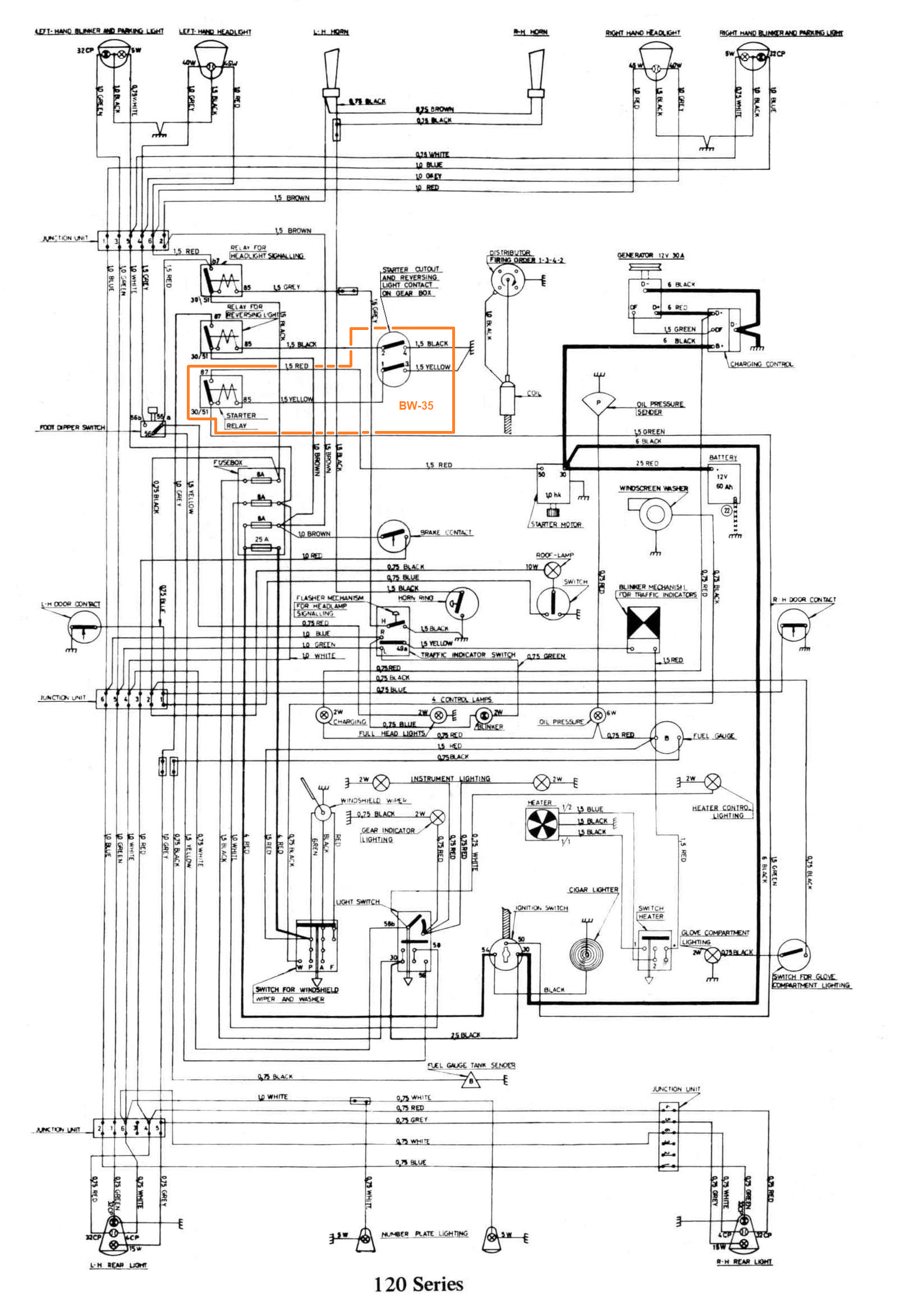
Disconnect vehicle battery before proceeding. Locate under the hood, on drivers side inner fender, the backing light control relay (grouped with possibly others). Trial mount the Headlight Control Relay in this area taking care to assure a good ground to the relay through the mounting hardware (scrape away paint) . Click here for a 122S Wiring Diagram as a reference (source: Intereurope 120 Series Workshop Manual), this is a detailed file and therefore fairly large. The Headlight Control Relay will functionally replace the relay shown on this diagram, and called "Relay for Headlight Signaling". It is shown with the "Reversing Lights", and "Starter" relays immediately above the fusebox. Remove relay again so that terminal numbers are clearly visible during wiring.

Simplified diagram for reference.
In addition to the Red (high-beam), Gray (low-beam) and Yellow (headlight power) wires of the old foot switch, taped and tucked into the harness in the area where wiring exits to connect to backing relay, can be found Gray (control), Red (high-beam), and Black (battery power) wires. Free the Gray and Yellow wires and connect to new Headlight Control Relay connecting per Upgraded 122 Wiring diagram below (use anti-corrosive paste on connectors). Notice, that we have TWO Red wires (actually three total, with two wires terminating in one crimp). These ARE in fact all the same. Leave the double wire taped and tuck back into harness, and connect the former foot switch Red wire to the relay. Finally we need to supply fused power. At the fuse block, the other end of the Black wire was not connected to Fuse 4, but typically tucked back into the harness sleaving. This wire will need to also be located and connected to the Fuse 4 protected (right) side.
Careful! Referring to Upgraded 122 Wiring diagram below, notice that there are TWO Gray wires shown connected to the upgrade relay. These are in fact NOT the same, and must not be mixed up...but they are easy to tell (and keep) apart. One is the control wire which was tucked into harness, and the other is the output wire supplying Lo-Beam power to the headlights, which is obviously in the relocated harness originally from the footswitch...generally vintage Volvos are pretty good about color code consistency, but not in this case...don't ask me why!...I guess there are only so many colors anyway...so at some point, one has to start reusing them.
When finished wiring the relay, double-check everything to verify it matches upgrade diagram below, and only after resolving any questions, neaten wiring, mount relay (use anti-corrosive paste on hardware to assure a good long-term ground connection), and proceed to next step.
Reconnect vehicle battery. The headlight flasher is supplied with battery power so is independent of the ignition. Lightly pull back on directional signal stalk. The new Flasher Control Relay should audibly close and the momentary contact should apply power to "brights" for as long as the stalk is held in the activated position...(even when headlight switch is OFF!). When headlight switch is in the headlights ON position, momentarily activating the relay, results in the "see-saw" contact applying power alternately to Hi and Lo beams...and note, that the position it is left in (Lo-Beam or Hi-Beam) when the headlight switch is turned OFF, will be the position it starts out in the next time headlights are turned ON (unless of course, the relay is momentarily activated for signaling purposes before then)...this all may sound overly complicated, but it really isn't...it takes all of operating it one time to get used to the way it works!
There...that wasn't so tough was it?

----------------------------------------

1800 Procedure
I'll get information and a procedure for the 1800s in the works (essentially the same as with a 122, but color codes are all different, plus the positioning the relay is a bit trickier on the smaller 1800 electrical panel)...but if your hot on doing this upgrade (I do have it on my 1800, and it works just dandy), please e-mail and I'll see about expediting it a bit...
----------------------------------------
The terms Volvo and SWF are used for reference only. I have no affiliation with either of these companies, other than being a customer and occasional mechanic/electrician on their products, in order to keep them working for me, and to help other enthusiasts try to do the same. The results presented here are from my own experience, and can be used (or not, and used strictly for your amusement!) at your discretion. As with any recipe, your results may vary! As always, if you can supply corrections, or additional objective information or experience, I will consider it, and consider working it into the next revision of this article...along with likely the odd metaphor and maybe wise-a** comment.
You are welcome to use the information here in good health, and for your own non-commercial purposes, but if you reprint or otherwise republish this article, you must give credit to the author or link back to the SwEm site as the source. If you don’t, you’re just a lazy, scum sucking plagiarist...the Boston Globe wants you!
![]()