
SwEm Service Notes and Experience R. Kwas
Continuously Updated, Last Update: 25 October, 2025 [Comments Added]
Also included are reprints of advice to e-mail questions or posts to inquiries on the (US) Brickboard.com or (British) Volvo Owners Club http://www.volvoforums.org.uk/forumdisplay.php?f=9 . or (German) Volvoniacs http://www.networksvolvoniacs.org/index.php/Spezial:AWCforum/sf/id2/Oldie-Technik.html Forums which the author frequents.
When you live with, use, beat upon, maintain and repair 122s and 1800s for more then 25 years, you cant help but develop some hints and techniques which make your work easier or more effective, or make the vehicle work better (and reliably) between servicing. I present mine here for the benefit of others, grouped by vehicle system. The advice here is intended to be used in conjunction with almost any of the shop manuals available. The most complete and thorough manuals are clearly the official Volvo green service booklets, bound together in a binder. But others, not quite so bulky, and more available, are also very good. My favorite: Intereurope Workshop Manual 162 (Volvo 120 Series, including 1800) ISBN 0-85666-066-3. Haynes and Clymer manuals are also available. Link to SwEm Library. To go along with with the hints and techniques, are also experience of using various products. Here is a page compiling those for anyone interested: Product Reviews. It includes the "Good, the Bad, and the Ugly."
Readers are welcome to submit contributions or comments (per e-mail). Naturally, and because of all the lawyers out there who need and are looking for work (Who said "If it weren't for lawyers, we wouldn't need them"?), combined with all the litigious people out there who would gladly give them work instead of taking responsibility for themselves, a disclaimer is also presented here:
The notes and advice published here are tried and proven and have been developed with the utmost of care, but are to be used at your own discretion and risk, and in conjunction with normal, careful shop practice. I cannot be responsible for your specific actions, or the direct or indirect consequences thereof - work (and drive) Safely! Ron
General: Vintage Volvos generally require the use of SAE Tools. Metric hardware was used strictly on Bosch supplied equipment such as the Starter, Generator, Distributor, Ignition Switch and Ignition Coil, VDO supplied electricals (instrumentation), and several places on the SU Carburettors.
Anti-Seize (AS) is messy but none-the-less very effective stuff in terms of long-term lubrication. The various manufacturers supply their own formulations, but since it generally consists of (most importantly graphite, but also nickel, copper, brass, and who knows what others...probably trade secrets...maybe bean dip) particulates suspended in grease, it has distinct performance advantages (obviously) over using nothing, but also greases alone, which can be displaced or deteriorate with time, or oxidize with heat, because while the grease may get baked away, the layered hexagonal crystalline graphite particles will not, as they are stable to well beyond 2000oF, and will continue to slip past one another. I use is just about everywhere, as a rule, and have yet to regret it...sometimes, like on rear brake adjusters, and lug nuts, it is essential! Link to Anti-Seize page.
Specific uses which make life a lot easier, and also allow proper fastener torqueing since sticktion is minimized: Head bolts, lugs/lug nuts (including the conical contact surfaces of the wheel), tapered ends of rear axel shafts, tapers of ball joint and steering rod ends, brake line ends and bleeding nipples, spark-plugs, just about any fasteners under the vehicle which are tightened and "forgotten" but none-the-less under constant moisture or salt attack. Thinned with light oil (such as Tri-Flow) preferred, or solvent, can be poured into control cables (Choke, E-brake), and locks for effective long-term lubing and anti-corrosion.
Anti-Corrosive Electrical Paste ...the electrical equivalent of AS! Most emphatically NOT to be confused with insulating dielectric grease, this is paste of fine conductive Zinc particles in suspension. It acts as a sacrificial anode for electrical connections, on a microscopic level, neutralizing corrosion, and creates a Gas-Tight-Joint, by encapsulation, thereby preventing electrical problems...use it!...the author has been for 20+ years with no regrets or recorded disadvantages!! Link to Anti-Corrosive Paste page.
______________________________________________________________________
Categories
Engine Motor mounts, Crankcase Breathing (PCV), Injector Blockoffs, Air conditioning, Adjusting Valves, Leaking Valve cover, Oil Coolers, Safety wire.
Fuel System SU Carburetors, Mixture Checking, Dashpot oil
Ignition System Reassembling/Checking/Static Timing a B18/20 Ignition system in disassembled or unknown condition (including Static Timing a B18/20), Checking for spark
Electrical Equipment DIN 72552 Terminal Designations, AMP light function, ("My AMP light came ON today!"), Simplified Starter Wiring Diagram, Failed Charging System Checks, Starter, Light Bulbs, Voltage Stabilizer (late 1800,140), Slow Wiper Motor, Fuse problems (25A shorty, also blowing F4), Gauges: 1800 (early) Tachometer Problems, 544/122 filled Thermal System Temperature Gauge, 122 Fuel Gauge
Front Suspension Checking Lower Ball Joints for Wear/Slop, Shock Towers Reinforcement
Braking System Hydraulics, Replacement lines and Fittings, Calipers, Pulling Drums, Other Notes on Drums, Manual Drum Adjustors, Brake System Upgrades and Modifications, LINK to: Brake Drum Removal
Body Locks and Keys, Broken Ignition Key, (Link to: Extracting a Broken Ignition Key), Door and Trunk keys, Seat suspensions, Early 1800 Fuel Filler, 122 Horn Switch Repair, Windshield wipers, Rain leaks under 1800 dashboard
______________________________________________________________________
Motor Mounts
[From www.Brickboard.com]...posted by Ron Kwas on Thu Feb 19 19:30 UTC 2004 ...in response to thread: "motor mounts" posted by Robert. Link to entire thread: http://www.brickboard.com/RWD/index.htm?id=757400
Robert;
Broken mounting bolts are not uncommon on that style bracket, when bolts vibrate
loose and allow bracket to wear away at the bolt sides, eventually fatiguing
them enough to break. Bolts are also in shear which really is not really right
(should really have pins like engine to bell-housing, where pins locate/are in
shear, and bolts hold everything together only).
...bottom line is that the broken bolt remains are likely loose in block and
fairly simple to remove (Dremel a slot and unscrew). After extraction, check how
badly threads have been damaged...down deep, they're probably OK.
There's not need to change to another manufacturer's mounts...replace motor
mounts (including trans mount which is also in shear) with higher durometer
Volvo mounts from 6 cylinder (PN 1206612). These work very well (and for a lot
longer!), and don't transfer appreciably more vibration to frame....just make
sure you use lockwashers and/or light duty "Locktite" on hardware into block to
prevent reoccurrence of loosening, which caused the problem in the first place.
Cheers
Additional:
Bob;
I mount them with the hex-plates down as I recall...
Did you make your measurements off the car or installed and under load? I expect
that the higher durometer (denser) rubber of the would compress less under load,
and this would result in the engine sitting slightly higher. As far as this (by
my rough estimate: not 1/4") being noticeable?...maybe by John, and also my
acquaintance who swears he can also hear the difference between 8 and 16 times
oversampling on a CD player...
Cheers
My response to a
![]() poster
complaining about premature engine mount failure:
poster
complaining about premature engine mount failure:
"...I've long ago stopped using the
engine/trans mount PNs called for the four cyl cars (add a bit of exposure to
oil, and they are not long for this world!), instead I only install the mounts
called for the six cylinder cars ...they are quite a bit stiffer (higher
Durometer Rubber!) and last MUCH better, especially in the rear Trans support
location, where they are not simply in compression, as in front, but also in
shear ...for PNs, see: https://www.sw-em.com/service%20notes.htm#Engine Good
Hunting!
Note...for those concerned with the 164
mounts transferring more vibration into the chassis, I can't say it is/was ever
noticeable to me...but I don't expect that would be the case with Poly
mounts...those maybe OK for racing, but in a normal roadcar, I would expect
you'd get sick and tired of the vibrations (and maybe having to replace
tooth-fillings so often!)."
--------------------
Adjusting Valves: Modify Feeler Gauge by "necking down" width to be less than the diameter of valves. This prevents bridging any wear-gap present in the rocker surface during clearance setting [see diagram!], which a full width feeler gauge does, giving a larger than accurate measurement (equal to feeler PLUS wear depression), and chattering valves.

Its a minor point, but a wide Feeler Gauge can bridge any weargap,
and the resulting adjustment will be generous by the gap amount!

My .016" feeler gauge... necking it down also makes
it easy to locate... fast!
...and using it when checking and adjusting Valve Clearance makes for an
accurate adjustment unaffected by weargap!
--------------------
Crankcase Breathing (Positive Crankcase Ventilation - PCV)
[From www.Brickboard.com]... posted by Ron Kwas on Wednesday, 11 April 2001, at 10:10 a.m. ...in response to "High Performance [included questions on crankcase venting]" posted by Jeffrey L. Bandel
Jeffery;
Your crankcase breather and the oil filler cap are effectively the same place, the crankcase, and this is indeed wrong.
Those mean-old gasses in there are supposed to get sucked out of the crankcase (by plumbing to intake manifold) and burned, but as tired, high-mileage engines
start to get more and more blow-by (combustion gases and pressure in crankcase), which gets sucked/pushed into intake causing fouling, some owners disconnect
that path. I suggest PO may have changed the routing for this reason (unless he was just practicing some creative plumbing).
If you check your manuals, the path for crankcase ventilation should be as follows: Crankcase Breather/firetrap/PCV
valve is plumbed to intake manifold (oil-compatible line), which extracts crankcase gasses AND fresh air which is drawn in through hose connecting oil filler cap to air filter.
The more crankcase pressure resulting from blowby there is, the less fresh air gets sucked, until there is so much, that
crankcase gasses blow OUT of line to air filter and foul same (a clogged trap will contribute to this). One can see therefore, that crankcase breathing can lead to a number of problems if not working (or
plumbed) right.
...then again, I once saw an ancient B18 with a simple tube originating at the crankcase breather going up for a few inches, then turning and going down (presumably
to prevent splattered oil from just running out) and opening up to atmosphere at the
oil pan (ALERT, ALERT-call Janet Reno...oh that's right, she's out of a job!).
I call that an EPA Avenger Dump Tube!
If your engine is fresh and tight, there's no reason (including performance*) not to connect up a crankcase breather system to the intake (don't forget to include the
flame-trap (which keeps fire out of intake manifold and you from maybe launching those nice Edwardo Webers into the hood from below) and PCV valve (which
keeps backfires from REALLY pressurizing the crankcase, blowing out seals and god knows what else!) . Now the question is: Do you want to drill a hole into
your nice new Weber manifold...BTW, my TWM (Weber) manifold had a boss cast in for the purpose of connecting presumably
crankcase venting or getting vacuum to run a brake-booster.
Finally, *racers don't hook up crankcase breathing to the intake manifold...they ONLY want power-producing mixture coming into the cylinders and not
non-powerproducing crankcase gasses just along for the ride. They are however required by regulations to have breather plumbing, which is typically routed into a
catch bottle (commonly referred to as puke bottle) to prevent oil from getting onto the track and causing everybody problems.
Hope that helps.
Regards
----------------
Additional on PCV systems: Crankcase venting underwent a series of evolutions, from early open, atmospherically vented, identifiable by oil filler caps with no hose fittings; to fresh air entering into the oil filler cap (B18), mixing with crankcase gasses and sucked out of oil trap; to fresh air entering at oil trap, and crankcase gases being sucked out of the oil filler cap (B20). For details, go to: Positive Crankcase Ventilation (PCV) Diagrams and Notes
----------------
Injector Blockoffs [in response to e-mail question on what to do with injector ports when using one of these heads with carbs]
Actually, the B20F is the best breathing head, so what you are doing is not that uncommon. I've done this also, and used SUs with it - with fine result! To block of the injector ports, I made some (nice) keyhole shaped plates of 1/8 Alu. (pic attached),

which were held down by a single bolt each into the respective injector clamp holes (sealed with a bit of Permatek (or RTV) as I recall). This solution is more elegant than necessary...I suppose if you didn't care about the holes, and didn't mind enduring some comments (probably from me!) at the next Volvo meet, you could just thread them (at whatever angle they go in) with a 3/8 tap, and wang some appropriate bolts into the holes. Don't forget, there's no pressure (unless a backfire occurs), only vacuum, so nothing elaborate is required...just something which will endure the temperatures and seal well! By the way...wouldn't those ports be a great place to inject nitrous, or water, or magic dust?...hmm...just a thought!
------------
[From www.Brickboard.com]...... posted by Ron Kwas on Sunday, 20 May 2001, at 9:51 a.m. ...in response to "Air conditioner" posted by Mike Kanaly.Mike;
Perfectly understandable about needing MaxAirCon in certain areas of the country.
Beware, and I'm not certain about this, but the B18 on a '62 (if that's what it absolutely must be, or if that's what's available to you), may NOT have all of the mounting bosses in the casting, required for the bracketry and supports which the compressor and idler bearing mount etc. would need. I suggest you investigate this thoroughly (pre-purchase to avoid later disappointment)...but buying an entire system from someone like Gary in the other post and combining it with the (more efficient, modern) compressor from Bob Foltz (current VSA VP at 718-863-0964)...would be the way to go to keep you cool!
Regards,
-------------
[From www.Brickboard.com]... posted by Ron Kwas on Wednesday, 20 June 2001, at 8:56 a.m. ...in response to "Re: A/C" posted by leeb.Jim and Leeb;
True, up here in the "soggy NE", AC is real nice when you need it, but the downsides are many (an extra 50+ lbs. of equipment, engine strain, access problems, inadequate radiator, carrying all the stuff around all year, when you really only need it at max. one month). Its a tough call, but if you decide to go ahead, a modern efficient compressor is definitely the thing to install (custom bracket available from Bob Foltz current VSA VP at: 718-863-0964), and an alt upgrade is also recommended to supply the high current the mag clutch draws (see alt kit on SwEm site).
I've removed the AC systems on my 1800 and ES, and use the 260 AC technique (2 windows open, 60 mph)...at least we have two-way-sneeze-through-wind-vents in these cars which we can adjust for max air flow onto the occupants...that helps...so does a good deodorant!
Cheers
-------------------------
Leaking Valve cover. The OE sheetmetal valve covers can leak because of poor gasket sealing... and just tightening the bolts further does not help...often, it actually makes the leak worse because of the distortion of the sheetmetal it causes right at the fastener holes. The cast aluminum valve covers do not suffer from this weakness, but if one does not want to incur the expense of replacing the OE cover, reinforcing plates, which spread the force of the fasteners and prevent this distortion should be used. Clean the gasket areas on valvecover and head well for a new gasket, applying sealer, torque fasteners reasonably.

When using the OE sheetmetal valve covers, reinforcement
plates really help to keep down oil leakage!
Force-Spreaders installed:
...to prevent distortion of the Valvecover sheetmetal under the bolt-heads,
install valvecover force-spreaders, which prevent uneven gasket loading and oil
leaks.
--------------------
Oil Cooler 120-130 |
| posted by
Ron Kwas on Sun Jun 29 17:27 CST 2003 |
| Jerry; Original equipment Volvo oil coolers (more correctly oil to cooling system heat exchangers) were fitted to early 1800s (I'm not certain about 123s...don't think they had 'em). This was done because the operating temperature limits for the oils of the day would be approached/exeeded under some operating conditons. The additional cooling brought those tempeartures down to something the conservative engine designers, bless them, were happier with! On the other hand, in extremely cold climates, (an important consideration, considering the winter temps of the country of origin) the "cooler" served also to get heat into the oil sooner to help achive an earlier thermal equilibrium of the motor (and less wear). The temperature ratings of modern oils don't really require additional cooling, but it sure can't hurt to bring the oil temp down, since in addition to the (water) cooling system, the oil also serves to remove a fair amount of heat. Any turbocharged car should have a cooler. Even though modern bearing housings are typically water-cooled also, with the extreme heat that the oils are subjected to in the bearing housing, any and all cooling is welcomed! Modern generic oil coolers typically exchange heat to the air, so if they leak, at least you don't get oil into your cooling system (this never happened to me, but I understand it happened occasionally on Volvos with the o.e. oil/water exchangers). ["Occasionally" was too softly worded! At this point, I understand the Oil/Water Heat exchangers are NOTORIOUS for failing, so the best advice at this point is to retire them from service! See also: https://www.sw-em.com/Oil_Cooler_Notes.htm ] Advantages in short: Cooler oil is less stressed, probably has better film-strength, and so better lubrication qualities. Cooler oil wont oxidize/bake away important additives as fast. Increased change interval is possible. Increased peace of mind, knowing you're doing something nice for your hard working B18/20! Disadvantages: Cost, additional plumbing increases complexity, and is a possible source of leaks, although Aeroquip/Earls etc. teflon/stainless lines and fittings are totally reliable, and can be safety wired just to make sure they don't EVER back off! Good Luck with your decision. |
Notes when rebuilding engines. Safety wire:
Camnuts. Nuts fit quite loosely onto the threads of many replacement cams...I don't know the specific reason, but after a freshly rebuilt engine began making nasty knocking noises, a complete teardown revealed that the camnut was just pinging against the timing cover...too bad we didn't remove the timing cover FIRST while trying to locate the knock. I now safety drill and wire the camnuts to prevent this.
Placeholder for pic
In another "learn-by-doing" lesson, where the idler shaft of the oil pump backed out of the housing and resulted in a vented engine, I now safety wire those too! See also Tech Article: A Funny Thing Happened on the Way to My 200K Badge .
Placeholder for pic
______________________________________________________________________
General Moisture condenses in fuel tank, especially after winter storms (high humidity) followed by temperature crashes to well below freezing. Use gas line dryer as preventative on any fuel fillings when temp is below 20şF/-7şC.
Install pre AND post pump (see-through, cleanable) fuel filters. Install
Grose bowl valves (available from ipd, I have yet to see these allow fuel-bowl
to overflow) to prevent the dreaded external combustion
B18/20 syndrome. ![]()
SU Carburetors:
Link to separate page on SU carbs (this page is not yet coherent and clean enough to post).
What SU carbs sizes are recommended for what displacement and horsepower range? Link to SU application Chart
For lots more on Choke and mixture setting and checking see: Check your Choke Tech Article
Centering the jets of an SU. [These notes have been rewritten with in further detail and added to SU Jet Bearing and Supply Tube Notes as a new subsection of: Centering the Jet of an SU ] Occasionally, and usually only after carburetor work (with disassembly) has been done, the dashpots do not fall completely to the venturi. This is situation must be corrected, as it is typically caused by the Metering Needle making contact with the Jet (...and they should never!...both are of soft brass. and contact will cause wear and changing the critical dimensions of the needle, affecting the mixture. This is undesirable!). Jets need to be "centered", not in their clearance hole in the carb housing, but with respect to the metering needle). After lubing the jet mounting and adjustments nuts. Jet centering can be done by trial and error, but using a centering pin (CP) is preferred and makes quick work of this operation. Replace the CP with metering needle, replace dashpot, its return spring, and evenly fasten dome screws. Activate choke control to lower jet in its tube. The CP will fall into the jet tube if, and when it is centered. If it does not, loosen the To center Jet tube, loosen the Jet Locking Nut, adjust the tube position, snug the nut and recheck. Observing down the throat of the carb with a decent light may help determine in which direction the Jet Bearing needs to move in order to acheive alignment!
Centering pin dimensions in inches.


Metering needle replaced with a centering pin.

SU HS6 showing (upper arrow) Jet Locking Nut (18mm), and
(lower arrow) Mixture Adjustment Nut (15mm).
Reprints of Postings:
[From www.Brickboard.com]... posted by Ron Kwas on Monday, 18 December 2000, at 7:55 p.m. ...in response to "Re: Rebuilding carbs" posted by Joe W.Joe;
SUs are super for their simplicity...if you're a careful mechanic, study the
books a bit(Tuning S.U. Carburetters by Speedsport is my favorite...don't know
if it's still in print, ipd may have others or contact me for photocopies of
important pages) jump on in the water...its really not that deep and the
darned things only have about four moving parts each! A couple of hints
follow:
1. Upon removal from vehicle and disassembly, make notes on where individual adjustments are (choke, jet height, metering needle position in dash-pot, etc.) to help with the reassembly starting point. Pictures would certainly help.
2. Send only the housings and shafts to the machine shop, and don't mix parts from one carb to the other on reassembly (different colored marking pens or separate boxes may help).
3. Install a post pump fuel filter (JC Whitney has those nice Pirex glass see-thru/cleanable type), and Grose bowl valves upon reassembly (source: ipd)! I've yet to see these allow the bowls to overflow. Many times after working on the carbs, the tiniest piece of debris will cause the o.e. valves to stick, resulting in massive fuel overflow and possibly turning your B18 into an external combustion engine...bad form.
4. Check and adjust choke per article on swem site.
_______________
[From www.Brickboard.com]... posted by Ron Kwas on Fri Apr 26 13:44 UTC 2002...in resonse to: Su Carb leaks (on an B20/SU equipped 544 after a year of storage).
Chuck;
I have had this happen also at the first start of vehicles which had sat for a
while (and the bowls had certainly dried). Besides the obvious cause of
foreign particles (which George and I agree is prevented by pre AND post pump
filters) I believe additional problems can be caused by the no-octane goop/lacquer
that the EPA approved fuel turns into after six months. In the small orifices
of your lawnmower or snownblower, this is often enough to completely block
them necessitating a careful carb cleaning, but on our SU equipped cars, this
might just be gumming up the bowl-valves. I like the Grose-Jet bowl-valves
(and this is were George and I disagree), I have yet to see leaks from carbs
so equipped (he doesn't like them...I guess HAS seen them leak), but I
wouldn't hold it against even Grose-Jets if THEY leaked after a long storage.
Besides, if they didn't leak before the vehicle was parked, why should they
all of a sudden? Clearly, time has something to do with it!
As part of the prestart checklist for the start of a (long storage) Vintage
Volvo, I suggest removing the bowl lids and blasting whatever bowl-valves that
are installed with a good shot of carb-cleaner (a couple of times, with some
time in between, to let the solvent do its thing!). You may find, this will
prevent bowl leaks, and the resulting dreaded external combustion B18
syndrome! A year is not that long of a storage time, so although definitely
down on octane, the fuel in the tank is probably still OK (but some
preignition may occur on that salad oil (thanks EPA)...top up tank with fresh
fuel at first opportunity), but prefilling the bowls with fresh fuel will do
wonders for getting it started the first time. Hmmm, "Reviving
a 'decommissioned' Volvo" sounds like a good subject for a SwEm tech
article.
_______________
Link to additional info on mixture, Lambda, and HC, NOx, CO emissions
(from the Charles Probst FI book).
[From www.Brickboard.com]...in response to: ...elaborating on mixture checking with road test... posted by JohnMc Thu Mar 21 18:16 UTC 2002
John;
I presume you mean to elaborate on the road test to check mixture not the original hot start string.
Doing a road test goes back to not having a dyne at my disposal...and this technique is my own and based on my experience (with a number of stock and performance moded 122s and 1800s)...appreciate that it is tricky to relate and that everyone's experience, and car is different... having stated my disclaimers, I'll try to explain my technique...
Non-rolling tests:
I find that once idle has been set (once off choke and fully warmed up), blipping the throttle should result in a decent response and rise in the revs...(in this case the engine is working against rotational inertia load only...the best I can do without a dyne and parked, so there's also no need to hold it at high revs...Important - the point is: The info is gained while getting to high revs, not by holding it there!). [A car with a lightened flywheel would respond faster, etc.] While doing this test, a lean condition will cause a
(noticeable) delay in the response, and a very lean condition can even result in (really
noticeable delay ) and bogging, and possibly even a lean backfire...and don't forget, this test is somewhat air temperature influenced...colder air would push the results toward the lean side...makes sense (cold air is denser [huh] and SUs being a constant velocity design have no mechanism for air density compensation)...that's why I find myself adjusting the jets down three flats for the cold season and back up three flats for the warm season (but other than that, I
don't touch my carbs except to check and add ATF to the dashpots once in a blue moon). BTW, I typically approach the optimum mixture setting (or at least a
satisfactorily performing one) from the lean side, and leave it set to where I get that satisfactory perf....so I won't cover the rich mixture result too much except to say that if you think you might be rich, back off on the jets in half turn steps, and redo the test...I think you'll find those
(noticeable) lean results fairly easily (and a road test would sure confirm this).
Road tests:
For checking the midrange mixture (probably the most interesting operating condition to me), I'll take the vehicle out on the road, and at a steady midrange speed, quickly floor the throttle (this is probably the maximum load I can put the engine under - up the steepest hill around is even better as it allows a prolonged highload condition...if I get a slow response, that suggests lean again (see above) and I'll richen both carbs by three flats. Obviously, this assumes ignition (including timing and advance) fuel system (including balance, float height, fuel pressure, metering needle selection, fuel delivery [i.e. no obstruction by sediment in bottom of bowl or some other
weirdness - I've seen it!]), and other little details like that are all under control and mixture is the only parameter in question at this point. Once you're close to being satisfied with the pref., pulling a plug after a prolonged run of a particular operating condition which you want to check,
checking the color against the published charts, will give you more info to base additional diddling upon...
Its clear to see that experience, judgment, and discretion play a huge role in this
adjustment business...doesn't that make a great point for all the things a modern fuel injection/engine management system does for you...sniffing all the temps, pressures/vacuums, your throttle input and whatever else, and looking up and dispensing just the right amount of fuel for each cylinder...most impressive when it works...then again OBDII never got anybody home when something crapped!
Cheers
---------------------
[From www.Brickboard.com]...in response to: I thought SU's called for ATF fluid. posted by Bryan on Tue Jul 30 17:31 UTC 2002
Bryan;
I believe they call for specific SU dashpot oil PNXXXXXX, costing who knows
what, and who knows if that is even (reasonably) available in the US (internet
search time!).
...it is critical to have light oil in the dashpot to slow and dampen dashpot
movement, but its pretty noncritical what you fill it with (watch some SU
specialist come and beat me up on this)...the oil does get slowly consumed, and
so needs to be replenished periodically... the important thing is the
weight/viscosity... ATF fits the bill nicely, so does Marvel mystery oil and
probably Vitaloni's Extra Virgin Olive in a pinch!
Cheers
______________________________________________________________________
Link to separate SW-EM Tech Notes Page
Revised Jan 2023
On earlier Cooling Systems without the Overflow Bottle, it is a worthwhile
and not particularly difficult change, to modify the system and add an Overflow Bottle, or
Expansion Tank, which accommodates
Coolant volume
variations caused by temperature,
Auto-Burps the system to keep it optimally filled and free of air, and
also allows a quick visual Coolant level check (the Tanks are translucent).
140 style
bottles fit nicely (there are variations, covered here:
Early/Late
Production Expansion Tank, Pressure Caps, and System Operating Pressures
) and are abundantly available (Tip: Get the
correct Pressure
Cap along with a used Expansion Tank.) Mount bottle next to radiator
using a custom made holder (a strategically formed welding rod wire will also do
this nicely).
PLACEHOLDER FOR PIC OF EXP TANK HOLDER
Conversion Details: When making this modification, the Pressure Cap, originally located on the Radiator seals system and allows system to pressurize, original Radiator Pressure Cap seal must be lifted off seat to allow unrestricted flow into and out of Expansion Tank. This can be simply done with a piece of soft insulated wire inserted into overflow pipe ([see picture below] not to block, but only to hold wire in place and partially around seat). After making this mod, pressure of Cooling System will be regulated by Pressure Cap on over-flow bottle.

(Early) Radiator filler with
Outer and Inner Sealing surfaces. The Blue wire visible
holds inner seat open and allows unimpeded flow into and out of the
Expansion Tank.
Link to cooling system thread: http://www.brickboard.com/RWD/index.htm?id=1218097
Note: When retrofitting an Overflow/Expansion Bottle, there were two different styles fitted, and the associated Pressure Caps do not interchange! See also: Early/ Late Production Expansion Tank, Pressure Caps, and System Operating Pressures
See also: The Radiator (Pressure) Cap
---------------------
[From www.Brickboard.com]...in response to "Cooling issues 120-130" posted by SébCH on Mon Jan 5 09:03 UTC 2004. Link to entire Thread: http://www.brickboard.com/RWD/index.htm?id=731762
Seb;
Those symptoms are pretty strange...so I don't have any immediate bright
ideas...but hot or cold weather shouldn't make that much difference as far as
the cooling system goes...that system is typically operating at more than a
hundred degrees above outside ambient, so during cold, one would expect the
cooling ability of the radiator to be even better (bigger temperature
difference) than during hot weather conditions, not worse...
I suggest you do a couple of things...test the tempgauge accuracy to determine
if those high temp readings are really "in the red zone" and something to be
concerned about...upgrade your cooling system to be a "sealed type", so that you
don't loose those 1-2 liters of coolant every time (hold rad cap off seat, and
add a tube and an overflow bottle to catch and return coolant)...determine if
there is good flow in the system (when the indicator shows hot, carefully feel
the bottom and top of radiator...if cold, flow, which is enabled by t-stat and
pushed by pump is suspect)...a dislodged coolant distribution tube in the head
might cause flow problems and/or localized boiling near temp sensor...
You did not state condition of heater valve...if you open this when indicator is
in the "red zone" (set heater to hot, and shed more BTUs from cooling system)
does this help?
I suspect some sort of flow issue, but that statement alone doesn't help much.
Prost Neu Jahr!
______________________________________________________________________
General: Particulate contamination from wearing rotor (carbon) center contact inside distributor cap promotes high voltage leakage to ground (especially during rainstorms, when everything under the hood including inside of dist. cap is below dew-point and condensate droplets occur on particulate contamination). Periodic cleaning minimizes this.
Apply lube (Placeholder lube name) to point shaft to minimize wear of follower. I'm certain this contributed to getting >50k miles on one set!
Centrifugal weights in base of dist. get hung up on support causing non-smooth advance curve and surging power. This took a while to find and is going to need pix to show!
Link to seperate Tech Article: Reassembling/Checking/Static Timing a B18/20 Ignition system in disassembled or unknown condition (including Static Timing a B18/20). This article includes pix of centrifugal advance (CA) mechanism checking and servicing.
Checking for Spark:
[From www.Brickboard.com]...posted by Ron Kwas on Wednesday, 28 February 2001, at 8:09 a.m. ...in
response to "How do I check for spark?" posted by ADN.
ADN;
Checking for high voltage leakage external to ignition components is very effective at night as Chris suggests.
You can disconnect, one at a time, plug wires and plug them into a spare plug which you then lay on the valve cover. This allows checking for spark with
the least intrusion on the system.
Also, if engine starts on three and smooths out after warming, start it, and shut off after 30 secs. or so and (carefully!) feel for heat at exhaust...this
will locate the nonfiring cylinder...try replacing plug first and try starting again, if no improvement, check plug wire and cap, especially at
problem cylinder connections.
Good Hunting
______________________________________________________________________
General: Probably a quarter of all the electrical problems on vintage Volvos can be, in part, attributed to poor connections. Sometimes these are caused by corrosion, sometimes from a loose terminal. It is important to make connections clean and snug. Penetrox/Noalox anti-corrosive paste on electrical terminals, including spade terminals, especially those under the hood or where they are not protected (like in front of radiator), can help prevent failures.
Link to my favorite product for keeping electrical connections working reliably for you: Anti-Corrosive Zinc Paste.
Link to my notes on: Care and feeding of Automotive Batteries
Link to my notes on: Curing Noisy Automotive Audio Systems
Link to: Lighting Tech article including upgrades.
Brake Lights: This is important safety equipment which should always be working...the bad news: Problems are known to exist!...the good news: Solutions are available! See: Brake Light Upgrades
Terminal Designations: Have
you ever wondered what those numbers on electrical terminals of a number of
Volvo components (mostly Bosch manufactured) are all about? They are
standardized [to a Deutsche Industie Norm (DIN) specification (DIN 72552)].
Link to a helpful extract from the spec.
Link to a more complete
listing (German).
The AMP light function: In the original configuration, the AMP light of vintage Volvos monitors the charging system by lighting when it senses a difference in voltage between the battery (by way of IGN switch and Fuse1), and generator output.
Normally, when engine is running and charging system is operating properly, there will be 12 Volts on both sides of the AMP light and the light will be OFF. That's right!...no voltage across means that light is OFF! But...if there is no Generator output and IGN is ON (like before starting engine), OR, there is Generator output and no Battery voltage (such as due to a blown Fuse1 or open associated connections), you'll see it lit.
Link to: AMP indicator ON tech article
What you should do if the AMP light goes ON while engine is running:
1. Check the easy things FIRST! Check for loose or broken fan-belt. Check the state of Fuse1 (the top, shorty 25A one). If blown open (especially if this can be associated with a spark or smoke while "working on", or hooking up something), replace with a spare fuse...if not blown, and you were just minding your own business, while driving along, as a quick test, try spinning the fuse in its holder...if this cuts through the corrosion present, restores the connection, and causes the AMP light to go out, you're in luck, but its definitely time for some anti-corrosion / prevention maintenance work on the fuse-block ASAP (and at the fat "battery" terminal of the starter couldn't hurt!)...and also time to read: http://www.intelab.com/swem/gastight.htm. If this does not help proceed to next step.
2. Using a multi-meter, and with Ignition ON (motor does not need to be running), measure voltage, first at right side terminal of Fuse1 (input from IGNITION switch), then at left side terminal of Fuse (output). It should be at the same voltage as the battery. If not, this must be rectified before proceeding to next step.
3. Check original equipment generator charging system for output. With engine running, connect a Multimeter across the battery terminals, and measure system voltage. At idle RPMs, the generator does not generate power, and so no voltage rise will be evident, but when raising the RPMs, the Voltage Regulator should activate the Generator with Field current, and a system voltage rise should be noticeable, as the Generator output raises the system voltage. If this does not occur, a problem exists in the charging system.
Failed Charging System Checks.
Checking the Generator:
A. Disconnect Battery.
B. Remove Generator and visually, check state of Brushes under inspection band. If they are worn down such that they are no longer taller than their holder, replace with new brushes.
C. Remove fan belt and with multimeter, check field resistance of Generator at DF terminal (to D+ terminal). X to X Ohms should be measured...less or more suggests internal problems. Replace Generator.
D. If known good components are available, Troubleshooting by Substitution of the Generator and Voltage Regulator may be helpful.
Running Generator as a motor...or "Reciprocity Test" Thanks to the principle of Reciprocity, a generator may be operated as an electric motor, by powering from the vehicle battery. This is an effective, quick way to check if it is OK requiring nothing more than removing the fanbelt and two test wires.
A. Remove fanbelt (Battery may be left connected normally). Check for free rotation by turning pulley by hand. High rotational resistance is a sign of mechanical problems, and should be repaired first.
B. Using a test wire at the regulator, connect Field terminal (DF) to Ground (regulator mounting).
C. Using a second test wire, connect Generator output terminal (D+ terminal at Regulator, labeled "Armature Terminal" in diagram following) to Battery Positive terminal (B+ terminal at Regulator ). This should cause the Generator to run as a motor at a low, even speed. If it does not, Generator may have worn Brushes, or an open Field or Commutator. If it runs proceed to: Voltage Regulator checks
Voltage Regulator Checks. From the generator internal circuit diagram following, it can be seen, that in order to control the (shunt wound) generator, the regulator completes the Field current path by connecting the Field Terminal (DF) to ground. Indeed, in the preceding procedure where the gen. is run as a motor, it is required to manually make this connection.

Placeholder for additional procedure
--------------------------------
Starting System Wiring Diagram: This diagram (source: factory Volvo service manual) shows this beautifully, but I've put together an additional separate Page on the Starter System.

-----------------------------
[From www.Brickboard.com]... posted by Ron Kwas on Wednesday, 14 February 2001, at 1:00 p.m. ...in response to "Re: blinded by the light - generator" posted by Danny.
Danny;
The AMP light comes on as a result of a voltage difference between the battery
positive terminal (by way of the ignition switch and fuse 1) and the generator output terminal. I suggest yours came on full, probably due to a generating system failure, although a blown F1 (or associated terminal or wire) will result in the same symptoms. In addition to checking f1 therefore (which I understand checked OK), you should check its circular contact points, terminals, and terminal connectors, preferably with an ohm meter. The
Intereuropre Workshop Manual No.162 has very good, indepth info on checking and adjusting the Bosch genny and its associated regulator, but the first thing you should
do after the aforementioned checks, is to extract the genny, remove its brush inspection band, and check the state and height of the brushes. At an advanced point of wear, they will not have enough contact pressure
against the commutator to give an output. You may be OK after replacing them. In the '80s, I saw Leif Andersen (at a Mount Snow VCOA meet) turn a set of worn brushes 90 degrees and reinstall them to
(temporarily) fix a charging system suffering from the worn brush problem. A cute, ingenious and very effective road fix!
Finally, I understand you need to put a certain amount of effort into trying to repair the charging system with its original components, but when you are done fiddling around with that genny/relay regulator based system, you should consider the alt/electronic regulator upgrade I developed. A lot of people are very satisfied with the result (see SwEm site). There is additional info in tech articles regarding the dim AMP light you also wrote of.
Good Hunting,
-------------
[From www.Brickboard.com]...... posted by Ronald Kwas on Monday, 28 May 2001, at 11:59 a.m. ...in response to "light bulbz" [original question regarding unusually high occurrence of lamps burning out on a 740 - this also applies to vintage Volvos - especially those sporting SwEm alternator upgrade kits!] posted by jay eden.
Jay;
Just exactly what did you check when you "multimetered" your car?
Unless you are installing incorrect bulbs, used bulbs (with unknown previous hours of use), are subjecting your bulbs to excessive Gs, or have somehow angered the gods and negatively affected your karma (not to be confused with a negative camber), you probably have an elevated system voltage! This is the likely cause of inordinately high bulb consumption as it will cause your bulbs to burn twice as bright for half as long (or some factor thereof).
Recall that your system voltage is
set by two factors [see also Tech Article: Electrical
Ramblings]:
1. Battery chemistry (temperature dependent).
2. The internal voltage reference of your voltage regulator. A bad ground on the
voltage regulator can cause this voltage to be "lifted" by some
amount. This in turn will lead to an elevated system voltage, battery
overcharging (and possible spewing of acid), and certainly excessive bulb
consumption. BTW, this ground connection may very well be (probably is) INTERNAL
to the alternator, although the external case ground of the alt. is important
too!
Good hunting.
------------
[From www.Brickboard.com] in response to "temperature gage" posted by someone claiming to be volvomex on Tue May 14 21:10 UTC 2002.
John;
I question your statement of the 140 instruments being more reliable...I'll grant you, the filled thermal system (capillary) tube temp gauge on my 122 is mechanically more fragile, but these are perfectly
adequate, and don't require ANY electrical power to operate - except for the lamp lighting up the
gauge!....mine have yet to fail, whereas I'd be willing to bet MOST original "Voltage Stabilizers" have died a miserable, electrically violent death long ago (taking gawd knows how many of the instruments with them as well!). I wonder what FMEA (Failure Modes, Effect Analysis) engineer signed of (if any) on that marvel of electrical engineering? [NOT!!] BTW...Was that thing made by Lucas?
Vo;
It really isn't that complicated...its just a heated bimetal cycling contact whose LONG-TERM-AVERAGE is 10V. It's output is continually
cycling between 12 and 0V...and that's the reason it starts of at 12V...the heating element has just been energized and so has not yet caused the contact to open. This module is located behind the big instruments (held in place by the same thumbscrew which holds on either tach or speedo...don't recall which). John is right...if they fail in the contact closed mode (12V out), your instruments are doomed! I recommend you loose it, and replace it with a solid state replacement available from
ipd.
------------
[From www.Brickboard.com].... posted by Ron Kwas on Sunday, 17 June 2001, at 4:21 p.m. ...in response to "Re: Erratic Oil Pressure and High Oil Temp" [ in a late production (injected) 1800, possibly caused by voltage stabilizer failure] posted by L K Tucker.
...I'm fairly certain, that since the original regulator was of a (slowly) cycling thermal element design, one would see either 0 or 12 Volts on the regulated output line, (the (long-term) AVERAGE of the line was 10V - this was apparently perfectly adequate for the instruments, which have an extremely slow response time). I gutted my 1800ES's when it failed, and replaced the thermal element with a modern fixed output electronic regulator [see below]. I would expect that's what the ones available from IPD have.
As far as the symptoms after failure...I would expect there to be two sets...one for if it failed at 0V output (supplied gauges would read zero) and one for if it failed at 12V output (gauges would read high).
Hope that helps.
Additional Info to this:
see: partial wiring diagram of '71 1800, showing voltage stabilizer. The unit is supplied from fuse No.4 (5A), along with the revolution counter, and brake warning, charging and oil pressure lamps. VS output supplies the coolant temperature, oil temperature, oil pressure, and fuel gauges, so (only) these instruments would exhibit the symptoms mentioned above upon VS failure.
[Placeholder for Voltage Stabilizer upgrade (to electronic regulator) info.] The circuit is a LM317 programmable regulator set for a fixed 10V output. Alternately, an LM7810 would be perfectly suitable. More info to follow!
Link to: Voltage Stabilizer output Study
---------------
[From www.Brickboard.com]....... posted by Ron Kwas on Thursday, 9 August 2001, at 10:26 a.m. ...in response to "wiper motor replacement" posted by Randolph.
Randolph;
A slow wiper can be caused by among other things, a low voltage to the motor caused by a corroded fuseblock (specifically a voltage drop across F1 and associated connections, which supply the wipers). I suggest you check the voltage to the wipers (engine on, wipers on, at fat red wire at wiper switch). It should be at least 12...better yet 12.5. If low, and caused by fuseblock corrosion, or your AMP light comes on a lot with the blower, it is time for a fuseblock rework!
Also check around for what may be getting hot (other than the wiper motor). This indicates a poor connection (which is dropping voltage and dissipating power which should be going to the wiper motor).
See also Gas-Tight-Joint on SwEm site.
Good Hunting
---------------
[From www.Brickboard.com].... posted by Ron Kwas on Wednesday, 7 November 2001, at 7:22 p.min response to: Fuse questions...(regarding F1) [120-130][67.5] posted by mario
Mario;
As Jim writes, it's the (almost) famous (shorty) 25A fuse...don't ask me why its the smallest fuse in the entire fuseblock when its one of the most important (powering wipers, fuel guage, OIL, and AMP lights), and they are getting tougher and tougher to find. Also, if yours does not have the conical ends, that's why it doesn't stay in place...it is NOT the correct one, but probably the nearest thing someone could come up with. If you locate the correct replacement, great. If not, the fuseblocks can be modified to accept the more common and readily available 3AG (1/4" X 1-1/4") fuses. (I also have these available, check SwEm site.)
An emergency road repair is to buy a modern spade type fuse holder with pigtails, plug in a 25A fuse, and install 1/4 spade crimp terminals on the pigtails. Plug the pigtails to the terminals on either side of F1. The current will be passed through the spade fuse and will keep you on the road until permanent repairs can be made.
Cheers
-------------
[From www.Brickboard.com]... posted by Ron Kwas on Friday, 7 December 2001, at 10:03 a.m. ...in response to "Fuse problem" [continuously blowing Fuse 4] posted by macglade.Mac;
Its highly doubtful, that installing an alt. can directly cause the blowing fuse...and upping to a 16A fuse is asking for trouble! Does your "mechanic", "friend" [who suggested this] change jobs a lot - just wondering?
Unless you've added loads to this circuit (like restoring the headlight flasher relay), this fuse protects ONLY the courtesy light circuit (5Watt bulb or so drawing at max around .5Amps!), so start by checking there (the little ball bearing in the switch lever tends to fall out...maybe it, or the spring from behind it, is shorting out the feedwire)...also check at the passenger courtesy light and switch under dash that side.
As Jim suggests an Ohm meter is preferred...one with a beeper will work nicely...connect across load side of (open/removed) fuse, and ground...it will beep UNTIL you locate and remove the short.
If you don't have an Ohm meter handy...connect a bulb (brake light or similar) across (open/removed) fuse terminals...it will be lit, UNTIL you locate and remove the short.
Good Hunting! Please advise us of what you find!
-------------
1800 (early) Tachometer problems
[From www.Brickboard.com]... posted by Ron Kwas on Tuesday, 10 July 2001, at 9:02 a.m. ...in response to "tachometer" posted by Bill Neff.
Bill;
One common cause of generous (early 1800) tach readings, is a poor connection of slider of its calibration potentiometer. (Carefully) drill access hole, mark slider position angle, apply a drop of Deoxid D5, rotate slider back and forth a bunch of times to clean and spread the D5, apply another drop, return slider to original angle (recalibrate if you need to have it perfectly accurate, but do you really get that close to read-line?), reinstall and behold the fruits of your accomplishment and workmanship!
I haven't yet tried to get anti-corrosive paste into this pot, but would expect this to work even better, as it gives a gas-tight-joint on the slider connection whereas the Deoxid will eventually need to be reapplied.
Alternative: Open tach completely, measure pot, slider position with Ohm-meter, and replace that pot with fixed resistors which will NEVER AGAIN get intermittent (opening up the tach requires beating up the case pretty good though)...maybe not such a good idea.
See also: Gas-Tight-Joint tech article and Service Notes section for more details, link below.
Cheers
----------------------
[From www.Brickboard.com]... posted by Ron Kwas on Tuesday, 27 March 2001, at 1:49 p.m. ...in response to "Overdrive working?" posted by David West.
David;
All this discussion about gear ratios and overdrives is OK, but...may I suggest another cause of your high RPMs ...a generous tachometer! This is a wellknown condition caused by an oxidized slider on its internal calibration pot [see below]. I'd suggest verifying the accuracy of your tach...I wouldn't be surprised if you found your tach to be 25% (or more) optimistic! 1800s are noisy and you might be easily tempted to believe what it was indicating.
Good Hunting.
 |
1800 tachometer with hole drilled to allow access to internal calibration potentiometer. This is a perfect place for a drop of Deoxit D5 referred to in Gas Tight Joint tech article, when accuracy is checked and adjusted. Also visible is (black) plastic hole-plug to close access hole (of course, duct tape would work just dandy too!). |
Link to: Smith's Tachometer Information
--------------
544/122 filled Thermal System Temperature Gauge
[From www.Brickboard.com]... posted by Ron Kwas on Monday, 10 December 2001, at 7:34 p.m. ...in response to "how hot is hot? temp gauge test" posted by Mario E.Mario;
Your test [Removing sender end and submersing into test bath of boiling water] is just about the best test you can perform on this system. If the gauge is off the dash, you will also see the calibration mark for 100 deg. C at the edge of the gauge (this mark is also visible with the gauge installed in the dash if you use some extra light). If the needle doesn't point right to the cal mark with the sensor in boiling water, it's not the end of the world...just make a mental note of where the needle IS pointing as a reference.
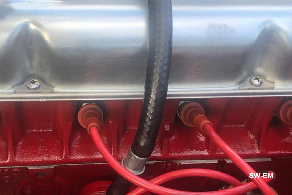
The temp sensing system is a "Filled Thermal System" type. That is, a capillary tube which connects the thermally caused pressure of the filling liquid (purported to be ether?, but could be Absolut Citron for all I know), to the gauge - no electricity required - but as soon as the tubing is compromised, it's toast...so just about anything you can do to mechanically strain relieve the tubing is great (the braid is just a protector so tape or a wire wrapping would be fine). Obviously this also means the entire system may not be taken apart for installation, so the gauge needs to be installed and the "sensor" (really just a plumbing fitting at the end of the pipe) GENTLY routed through the big hole in the firewall when installing.
Also, I like to start an engine (the first time after the cooling system has been apart), with the radiator cap off (and watching the temp), so that I can top off the system after the thermostat opens and the radiator level drops.
Cheers
----------------

544/122 temperature gauge showing calibration marks
From another Brickboard Posting on the same subject: The temperature sensor, connecting tube and gauge are a sealed, single assembly, and if the gauge needle is indicating at all, can be considered to be working...the exact accuracy of the needle is another story...but this may be checked... by removing the sender from the rear of the top of cylinder head (carefully, without compromising the capillary tube), placing it into a Styrofoam cup, filling the cup with (truly) boiling water, and noting the displacement of the gauge needle. There are calibration marks on the upper edge of the gauge face (use a flashlight and look from below to see them), the high temp cal mark (100 deg. C) is pointed to when needle is in middle of upper white region. If that's not were the needle winds up, it's just age making itself known, just make a mental note where it IS, and keep that in mind later, when everything is back together. Adjustment of the Bourdon tube (actually a pressure gauge) needle is possible, but I don't recommend it for the inexperienced or those not comfortable with micromechanics.
This temperature indicating system is very good
in that needs NO electrical power, and has a virtually instant response
time...so can show the temp drop as you raise the revs and coolant circulation
improves...this is perfectly normal, but I would make sure your thermostat is OK
and cooling system can hold pressure, which makes it more efficient. Yes, it IS
a bit disconcerting to see the temp needle take off toward and into the red
(white) after shutting OFF the engine, but it's perfectly normal, because as a
filled thermal system not needing electrical power, it is still indicating after
the engine (and therefore coolant circulation) is shut OFF.
-------------
122 Fuel Gauge
Fuel gauge uses the VDO supplied balanced magnetic "drehspulinstrument" indicator. Link to: VDO indicator data sheet
[From www.Brickboard.com]... posted in response to "Sending Unit" posted by Joe W on Tuesday, 9 October 2001, at 1:17 p.m.
Joe;
The 122 fuel gauge system has a very fast response time as it is NOT highly dampened
to
smooth out readings (as on modern cars (even later Volvos with the infamous Voltage Stabilizers) where you typically have to wait a few minutes after filling the tank for the gauge needle to rise and the full tank to be accurately indicated...or totally electronic cars where you may even need to cycle the ignition for the computer to make a new interrogation of the fuel sender). This causes relatively fast float changes such as fuel sloshing on cornering to be indicated as a bouncing needle.
If your needle bounces consistent with sloshing fuel, no problem, but if your needle bounces even
faster and/or "baps" up against the pegs at either end of travel, it suggests an intermittent connection possibly caused by poor contact on the float wiper.
I actually use this information...occasionally, when I get really low on fuel, I may give the steering wheel a fast flick from side to side...if I see fuel needle bounce indicating slosh, I know I still have a bit left and I'm OK for the moment, but if there is NO bounce at all, I know I better refuel IMMEDIATELY (no offense intended, but women wouldn't understand, their fuel gauge never drops below 1/2...why is that?). Of course, this effect is
naturally also a function of the gauge adjustment, but I actually like mine adjusted like this.
Luckily, I've never gotten stopped for doing this trick in view of a police officer...I'd hate to try to explain my "erratic driving" as a "low fuel level check"...he'd probably have me doing a field
sobriety check in about a millisecond.
Hope that helps.
______________________________________________________________________
Link to: Wiring Diagrams and Related Page
| Online files | Notes, Excerpts: |
| 444/445 | 444/445 PDF |
| 544 (6V) | |
| 544/210 | |
| 122 | 122 PDF (This wiring diagram is of an vehicle with Automatic Transmission (BW35),so the Start Relay (which interlocks Starter Solenoid with Transmission to only allows Starter activation in Neutral) is shown, as well as a Headlight Signaling Relay (which was not fitted in the US but which can re retrofitted. For this, see: 122S Headlight Flasher Upgrade/Restoration |
| 123GT (US Spec.) | With a single Foglight and a single Spotlight. |
| 123GT (Euro Spec.) | With dual Foglights, electrically interlocked not to be available when headlights are on. See also detailed consideration of this: 123GT Consideration of Lighting Differences |
| 1800 | * Note: Light, Wiper, and Fan Switch internals shown on this and all factory Wiring Diagrams are oversimplified and not correct. When working on these circuits, use the correct switch information! See: 1800 Light Switch, Wiper Switch, Fan Switch Drawing Corrections |
|
1800E 71 1800E 71 Key |
Excerpt with
Instrumentation Power highlighted. Voltage Stabilizer Notes Tech Article |
| 1800E | Charging System Excerpt |
| 1800E | Rear Window Defrost Heater Excerpt |
|
1800ES 73 1800ES 73 Key |
Link to US version (includes DOT mandated Seatbelt Buzzer!), redrawn in color corresponding to wiring colors: http://www.networksvolvoniacs.org/images/5/50/Schaltplan_color_Volvo_1800ES_73_Mod_Y.pdf |
| 140 70 | |
| AM Radio (Bendix) | Link to: Radio Notes |
| Smith's Tachometer | Link to: Smith's Tachometer Information and Notes |
| Bosch D-Jetronic Fuel Injection |
'71 1800E:
http://www.sw-em.com/bosch_d-jetronic_injection.htm#71_1800E_Fuel_Injection_Wiring_Diagram
'73 1800ES: http://www.sw-em.com/bosch_d-jetronic_injection.htm#D-Jet_in_73_1800ES (Note Differences!) Both are a located at: Bosch D-Jetronic Fuel Injection Notes Compilation http://www.sw-em.com/bosch_d-jetronic_injection.htm |
Other Electrical Items:
______________________________________________________________________
Convert to silicon fluid. Machine slave piston and install o'ring. Wire-brush, anti-seize, protect adjustment rod at slave cylinder with rubber tubing to permit hand adjustment of nuts.
______________________________________________________________________
Mount to cross-member is under shear forces...normal part is overstressed. Install six cylinder (PN1206612) mount (made with higher durometer rubber) for more positive mounting (also on both forward motor mounts).
______________________________________________________________________
[POS!]...I feel sorry for anyone cursed with one of these, and the resulting decrease in performance! It turns a decent performer into a road-slug! I feel your pain...the black Amazon has one...I'm not proud of it.
Lock-out contact which controls Starter Relay goes intermittent and prevents starting (with gear selector in Park position). A temporary fix is to disconnect wires from terminals 87 and 30/51, and connect these together (which the energized relay would do), to allow starting. EXTREME CAUTION must be exercised after doing this however, since the starter lockout function is now bypassed and it will be possible to energize the starter in gear, thereby causing the vehicle to lunge. One must be absolutely certain gear selector is in Park position before energizing starter!
-----------------------
[From www.Brickboard.com]... posted by Ron Kwas on Friday, 29 June 2001, at 8:53 a.m. ...in response to "transmission bushing" [question regarding replacement of NLA bushing on auto trans shift linkage shaft] posted by steve viada.
Steve;
In another demonstration of the beauty of simplicity (of vintage Volvos), it turns out that this bushing can be perfectly replaced with rubber tubing!...from memory...I believe I used about 1 inch of 5/8 ID heater type hose (measurement of the shaft and hole would verify this quick enough), I put witness marks on the clamp and shaft, separated them to facilitate installing the new "bushing", pushing it onto the shaft, until it was halfway in the engine compartment/halfway under the dash, and reassembled (tubing is snug-fit, so clamp doesn't even need to hold it in place - but would)...worked Fine Business!
Sorry I couldn't give a more elegant solution, but you will spend all of about $2 (if you don't have hose in stock), and about a half hour on this fix!
BTW...my condolences on having an Auto trans 122...what a waste!...the only good thing is the O.E. 4.30 diff, which yields great off the line performance after a 4/5 speed conversion!
Cheers
[Placeholder for bushing pic]
______________________________________________________________________
Drivetrain: Blast and paint drive-shaft (during u-joint replacement session) to keep balancing weights from rusting and flying off.
[From www.Brickboard.com]... posted by Ron Kwas on on Fri Dec 5 14:23 UTC 2003 ...in response to U-Joint U-doo voodoo 444-544 Link to thread: http://www.brickboard.com/RWD/index.htm?id=717350
John;
I have to agree totally with you...there is absolutely no reason why a semi
capable and careful home mechanic shouldn't replace their own u-joint(s)...as
far as I'm concerned, it is an excellent beginning mechanic job with which to
get some hands-on experience...and at the absolute worst case, if you ruin a
u-joint (if the needle bearings fall over while squeezing the cups in place and
you didn't notice and kept squeezing), it MIGHT cost you another $15 for another
one...a cheap price for all the experience gained. It's a perfect
Saturday-before-lunch job!
JME;
Voodoo? There is none!... here's a couple of pointers:
Use a hammer and drift to pound out old cups, but use a less violent, more
controllable method like an arbor press or bench vice (the larger, the better)
to press in new cups (after applying a bit more grease into the cups and
adhering the needle bearings to the cup walls with it). Naturally, I personally
would used anti-seize to install cups into the yokes (makes a big difference
getting them out next time around).
Beware: On u-joints with zirk (grease) fittings, (and this may just be on
some applications) there is only clearance to put the cross in one way because
of that zirk fitting.
While drive-shafts are out, is THE time to inspect/replace as req'd, the bearing
and rubber components of middle support.
When installing drive shafts, keep all crosses in line with each other (George
may chime in, and explain geometric reason for this), and apply a bit more
grease into the spline joint (I use anti-seize here also because my splines are
worn and I figure the particulates which don't get as easily displaced, help pad
the free play) [see post reprint following].
Rebalancing would not hurt, but is NOT required!
Cheers
------------------------------
[From www.Brickboard.com]... posted by Ron
Kwas on Saturday, 31 March 2001, at 3:58 p.m. ...in response to "I'll check
the bushings" [original question regarding clunk when going from drive to
decell] posted by David West.
David;
I haven't seen anyone mention slop in the drive-shaft spline joint yet. My Snow-Weasel '66 Amazon (with 230kM) has a
noticeable clunk (when changing from forward to reverse drive and visa-versa) caused by this...and it occurs a bit more
noticeably after the vehicle was parked in gear and presumably the grease has taken a
set to one side. Its tough to verify with driveshaft in situ...but try grabbing shafts either side of spline joint and applying opposite rotation force -(rear wheels of the
ground). It would obviously be easier to check for this with driveshaft off vehicle. If you find you have this condition, don't be too concerned - it'll run fine that way for thousands of miles
more, but anti-seize with its particulates will pad some of this slop and I highly recommended it for reassembly.
[Ever hear of the
hand-full-of-sawdust-in-the-slipping-automatic-transmission-trick...same idea!]
Good Hunting
______________________________________________________________________
______________________________________________________________________
Checking Lower Ball Joints for Wear/Slop
[From www.Brickboard.com]...posted by Ron Kwas on Thu Aug 30 15:34 CST 2007...in response to: "Steering really hard on a 122s" Link to Brickboard Thread: http://www.brickboard.com/RWD/index.htm?id=1211364
Jeff;
The upper bjs are not loaded nearly as heavily as the lowers...they just
basically locate the upper end of steering knuckle...that's why they're smaller
and rarely go bad...the lower bj can be checked by using your Tommy bar (or
another possibly larger, longer lever) to check for slop by levering against the
two parts...it's not an exact science because the whole assembly is under
serious tension from the spring...and you also wouldn't want to damage the boot
in the process...and you'd only see the slop once it was a lot and the bj
certainly would need to be changed then...a small amount just might not be
easily detected...
...(lets see if I get this right) on the top of the spring rests the corner
weight, the bottom of spring is connected to the lower A-arm, but the spring is
compressed between the two A-arms, so the net effect is that the lower ball
joint is constantly under tension (this is also why the lower A-arm falls to the
ground semi-harmlessly with a lower bj separation).
The best and most accurate way to check the lower bj is to release the spring
tension from the assembly and bj, then check it...remove wheel, jack up corner
supporting lower A-arm...support vehicle at frame (crossmember)...loosen (old)
castellated nut or (new) nylock, when fully loose, gently lower the lower A-arm
a bit, allowing knuckle to separate from bj...if it doesn't immediately on its
own, help it with some taps...once separated, lower the lower A-arm with jack...bj
is now free and able to be checked. Assembly is as they say, the reverse of
disassembly.
If it was me, I'd drill and thread in a zerk fitting (from below) which would
allow greasing. Maintenance-free is just another name for unmaintainable!
Good Luck
Shock Towers Reinforcement (122/1800)
Even Swedensteel fails after a few million poundings by the Shock Absorber! Shock Tower fatigue such as seen here is not uncommon (but you can reuse the Shock Absorber!):

Ulf Jonsson picture used with his kind permission.
My response to a thread on the subject: "If the triangular patch is greater than double the thickness of the cross-member, it will probably hold just fine (as noted by other posters) but back in my younger day, I agreed with you about having the weld in shear instead of tension and banded the repair up/over/down as shown (I probably wouldn't do it like that now)..."

My reinforcement technique. Probably not necessary!
This reinforcement is fine! George Swift picture, permission to repost requested. Nice welding job, George!


Someone else's shocktower reinforcement. From Instagram, uncreditied (no
surprise!).
----------------------------
[From www.Brickboard.com]...posted by Ron Kwas on Tuesday, 24 April 2001, at 8:44 p.m. ...in response to "KYB Shocks" posted by Carl Bauske.
Carl;
I've got KYBs on an 1800 and 122, both with ipd stage two suspensions (front/rear bars but oe springs), and an original suspension 1800ES, and I can say that I'm perfectly satisfied with all of them...and I do like to use my suspensions fairly hard. If I had to race the car though, Bilsteins would definitely be the way to go, but for a third of the cost, I'm happy with 80% of the performance!
One thing though...for as long as I own my cars, the original white paint on them doesn't last for s***...I recommend brushing on a couple of good coats of Rustoleum white to keep them looking nicey-nice...don't forget, they are guaranteed for life (last time I bought some)!
Regards,
______________________________________________________________________
______________________________________________________________________
Anti-Sway bars: Installing ipd anti-swaybars results in a noticeable decrease in body lean during cornering, without sacrificing general ride comfort (spring rates remain unchanged). Modern tires are also capable of taking advantage of the improved cornering ability. When installing bars, reinforcements are required on both front and rear bars, but not included in the installation kits.
[From www.Brickboard.com]... posted by Ron Kwas on Monday, 18 December 2000, at 8:13 p.m. ...in response to "Rear ipd Sway Bar Installation (122)" posted by I.H..I.H.;
Congrats! You will LOVE the difference in the way the car feels the first curve! Upgrade to double bolt saddle bracket in front if you have only single bolt type. [Link to Nagging Clunk article] When installing the rear bar, a reinforcing plate is a MUST!...a 5X5" 062" thick plate, bolted in the corners to the floor under the rear seat is perfectly adequate, without it, the bolt WILL rip out (been there, done that, took pictures...lost 'em). As far as the bolt length from the rear to the body...I recall its about 5" (which makes the arms of the bar approx. parallel to the vehicle floor, but ipd might sell you a whole bolt/bushing kit, try them!
[E-mail response to further
question regarding "saddle bracket".]
I'm referring to the two saddle brackets (with bushings around bar, R+L), which mount the bar to frame (not the two long
bolts with 4 bushings, which connect the bar-ends to the lower A-arm). Look under front of vehicle...you can't miss them.
Two types were used-single and double bolt types (I believe these are part of the mounting kit which was mentioned on
brickboard as being available separately from ipd...this is probably a worthwhile thing to get...double check what the kit
consists of). The single bolt type WILL tear out (been there, done that also).
[Link to Nagging Clunk article] Frame MUST be upgraded to accept two-bolt
type...some welding is involved.
______________________________________________________________________
Steering Coupling Replacement 122
Note: There is only a small hole in the bottom plate of the steering box of 122 and 1800 models (to allow the horn wire to pass), which is difficult if not impossible to find blindly during reassembly, after the horn wire is pulled up and out during (old) steering coupler removal. This procedure covers the addition of a pull-wire which makes the replacement a lot less difficult.
1. Disconnect vehicle Battery.
2. Loosen coupler hardware after making alignment marks on lower and upper shaft clamps.
3. Cut wire below steering box allowing enough slack to work with end, and solder on 1 meter long pull-wire.
4. Remove hardware and extract coupler from between shaft clamps (once hardware is removed,
upper and lower steering shafts can be misaligned to help with this). Pull coupling away,
and pull oe wire along with pull-wire from between shaft clamps until soldered joint is
accessible - Don't loose pull wire at steering box end!
5. Desolder oe wire from pull-wire leaving both wires in place.
6. Prep new coupling with silicon and insert spacers from 4 radial holes of old
coupling (see pic).

Old and new steering couplers showing inserts.
7. Thread oe wire through center hole in new coupling and resolder pull-wire to oe wire.
8. Using pull-wire, pull oe wire back down (until soldered joint emerges from steering box) as coupling is aligned between shaft clamps.
9. Reinstall hardware at coupling ( 4 radial spacers prevent over-torqueing), restore connection of oe horn wire (14 ga. crimp).
10. After all work has been satisfactorily checked, reconnect battery, and with ignition on,
check for horn function.
The 1800 models use a different style coupling requiring different couplings to the Steering Shaft, but the technique is essentially the same:
-------
If the old Horn-wire is cut or no longer in-place so it can be used as a "pull-wire", install wire, it should be threaded from the bottom up, as it is near impossible to find the "small pipe within a big pipe" when working from the top down! See also: Reference Information: Hornwire Replacement
If you insist on working from the top down, it might take you an hour...

Link to video of Steering Box rebuild: https://www.youtube.com/watch?v=TwqFLOxVYs0&t=1331s
______________________________________________________________________
Hydraulics: Convert to
silicon fluid. Rebuild hydraulic components with silicon grease
(compatible with Girling natural rubber seals). Link to separate
SwEm Tech Article on
silicon fluid. If single braking
hydraulic system is compromised
![]() , one
only has the mechanical emergency brake as a
back-up. For this reason, the brake system including rubber and metal
lines, should be carefully inspected yearly. Prime and paint metal brake
lines to protect them from rust.
, one
only has the mechanical emergency brake as a
back-up. For this reason, the brake system including rubber and metal
lines, should be carefully inspected yearly. Prime and paint metal brake
lines to protect them from rust.
Replacement Lines and Fittings: In Europe, Kunifer, a non-corroding alloy of copper, nickel, and steel is popular with restorers. It is purported not to be expensive...I don't know if this is available stateside, but it would seem to be worth investigating...(apparently Volvo has been using galvanized brake plumbing since '71, and the Kunifer alloy C70600 alloy since '76)! [Interesting reference reading: http://64.90.169.191/applications/automotive/brake.html and http://64.90.169.191/applications/automotive/931028-automotive-brake-tube.html ]
Link to Kunifer info: http://www.bannemer.de/shop1/index.html
Calipers: 122 and 1800 Calipers are the same ones used on Jaguars (E-Type, XJ6, XJ12) Stainless Pistons (oh goodie, no more pitting - ever!) are available from: John Farrel Auto Parts , (I have no first hand experience with this outfit, link is presented here strictly for info, anyone who can report on their experiences with this outfit is requested and welcome to e-mail us with their experience - Thanks!). By my inspection of their SS piston part numbers, It would appear that the big piston (2.125" dia. one required per caliper) is PN 64325561 / 19-1208, shown listed at $25.50ea., and the small piston (1.50" dia. two required per caliper) is PN 64325434 / 19-1225, shown listed at $24.50ea.
[On Brickboard, see also: Caliper pistons for Girling rear disk brakes [120-130] posted by someone claiming to be Chris Noyes on Sat May 3 01:54 UTC 2003]
Brakes Thread: http://www.brickboard.com/RWD/index.htm?id=713703
When rebuilding calipers, removal of pistons can be extremely difficult, especially if they are pitted and possibly even "seized", after not having moved in a loooooong time (even when in service, they don't move a hellova lot!). Demount caliper, leaving brake plumbing intact, remove from disc, and use the tremendous hydraulic advantage of the braking system to push the pistons out (use some custom cut, strategically sized and positioned wooden blocks to hold individual pistons, and to focus hydraulic forces just to one piston at a time (but keeping them from popping out totally) - because remember - once a single piston pops entirely out of its bore opening the hydraulic system (spewing fluid all over the place), it will be impossible to make any pressure to "persuade" the remaining pistons out!. If the caliper is already off the vehicle, and removed from hydraulic system, the pressure advantage of a master cylinder on the workbench is still hard to beat for removing the pistons... plumb caliper up (start with shop air, and when it is clear that this is woefully inadequate, use a spare master cylinder) to get the hydraulic advantage over pistons...trying to do it any other way is probably damn near impossible! Once the pistons are out, clean and inspect...pitting will probably be evident in the area outside the seal but under dustboot. Pistons with pits should at the very least, be polished and rechromed, or otherwise replaced (see above for the SS replacements), but definitely not be reused as pits will not allow a good seal, and will tear up a new seal in short order.
Link to Brickboard thread: Caliper reseal 120-130
Naturally, after blasting and painting calipers, I recommend rebuilding them with silicon grease on the pistons, rubber seals and dustboots, to go along with the silicon fluid which you will hopefully be upgrading to!
[LINK to: Brake Drum Removal, Inspection, Reassembly Notes]
Pulling Drums: Use impact puller of the type shown to release drum from tapered axle shaft. Sometimes, removal can require quite a lot of force. With this puller design, three arms are securely connected onto lugs by lugnuts, and the threaded center rod pushes the assembly off the shaft with continuous, but more importantly, tremendous impact force, as the double ended wing-wrench is struck with a 3lb. hammer. Often, this is just about the only type of puller which will impart the force necessary. Pullers which grab around the edge of drum will likely break that edge off before releasing drum from axle shaft and should most definitely not be used...EVER!

Impact Puller

Here is a
pic of another acceptable style (homemade - nice job!) puller. It uses the
same principle of attaching to the lugs, and is even nicer in that it is just
about impossible to misalign. Picture used with permission, thanks and
credit to Martin "Mcoldie"
of the German Volvoniacs Forum.
A few notes on drum removal: After removing cotter pin and castellated nut, and before attaching puller, turn nut around and thread back onto axel, until it just reinforces the end of shaft...this prevents mushrooming shaft end if you really have to apply mega-force. If damaged, use three corner file or 7/8" UNF threading die to repair threads, Link to Brickboard thread on damaged axel http://www.brickboard.com/RWD/index.htm?id=713791 Also, with the forces involved, bent lugs can result if things are not straight, so make damn sure puller is on STRAIGHT before pounding the bejesus out of puller (which a real tough drum may very well require for removal)...be sure arms which attach to the lugs are on to a similar depth, and the threaded pushing shaft is centered on axle. Loosen handbrake when pulling a rear, and loosen adjuster, if free. If you get a real stubborn one, heat center area with a torch while continuing to pound...
Other Notes on Drums: No matter how easy or tough it was to remove a drums, after finally getting them off, grind "wear-lip" off drums to ease future removal. The "wear-lip" develops as the shoe friction material wears away the drum slightly inboard of the drum edge. When the drum needs to be removed, shoes bump into the lip making removal more difficult. See illustration. If adjustors are free to move, backing off adjustment will withdraw shoes also, making it easier to clear the bump.

Sandblast/paint (outside surfaces) with high-temp (barbecue) paint...drums are No Longer Available (NLA) and/or expensive. Naturally...apply anti-seize on tapered axle shaft to ease future removal!
Manual Drum Adjusters: The first time drums are removed for brakework, it is absolutely necessary to rebuild adjusters using anti-seize. Often, drum adjusters are stubbornly frozen, seemingly better than welded...and if a simple open-end wrench is used to try to adjust shoes, rounding off the 1/4" square adjustment peg will surely result.
Frozen adjusters occur because they are especially susceptible to galvanic corrosion and freezing because housing is aluminum and adjustment screws and cams are steel (not such a good combination of materials in direct contact over the long term), the anti-seize acts as an effective lube and electro-chemical barrier, preventing future problems. If already frozen, use any method from prolonged oil/penetrant soaking, to brute force to completely disassemble adjustors, wire-brush to remove all traces of the aluminum oxidation before reassembling with liberal amounts of anti seize. Adjusters will now remain operational for a very long time. Link to Anti-Seize page.

A rebuilt, anti-seize prepared drum brake adjustor and custom adjustment
wrench made with standard socket wrenches and sockets.
A 3/8" socket wrench set up with a 3/8" hexdrive (the same one a vintage Volvo mechanic might already have in the tool collection for the transmission-to-bellhousing bolt removal), then brought down to a 1/4" square drive with a normal socket, makes an effective adjustment tool which contacts all four sides of the adjuster and prevents rounding (but only if adjuster is free to turn in the first place).
Brake System Upgrades and Modifications: When in good working condition including adjustment, vintage Volvo brakes work adequately well for all but the most demanding driving. None-the-less, an owner might consider making them better. Link to an interesting discussion on upgrading a typical disc front/drum rear system: http://www.brickboard.com/RWD/index.htm?id=656745. Another: http://www.brickboard.com/RWD/index.htm?id=753669
Brake Lights:
This is important safety equipment which should always be working.
...the bad
news: Problems are known to exist! Check for brake-light function
often! See: SwEm (Safety)
Bulletin Number 4
...the good news: SwEm Improvements are
available to eliminate unreliability! See: Brake Light Upgrades
____________
Additional info on brakes:
[From www.Brickboard.com]... in response to question about "122 soft pedal"
dv;
Do you really mean a soft pedal (time for bleeding!) or that the pedal needs two
long excursions before it becomes nice and solid and good braking action
results...because with 5-6 clicks of free travel before the rear shoes contact,
(which is on the high side), I suggest you should adjust the rears a bit
closer...I think you'll find that will help eliminate the free travel, and the
E-brake will work at around 3-4 clicks.
The very effect you describe, is just the way I know that my rear shoes need adjusting, but usually, before I get an opportunity to climb under the rear and adjust, I just preload the E-brake a couple of clicks...remember the adjustor manually spreads the bottom end of the shoes, and the E-brake spreads the top end...either way brings the shoes closer to the drum and therefore results in requiring less wheel cylinder/master cylinder action.
Cheers
____________
[From www.Brickboard.com]... in response to question about fitting "new brake lines"
Linc;
Use this info only if you're comfortable working on your brakes....but if you're
a decent, careful mechanic, there's no reason why you shouldn't...it really
isn't rocket science...besides, who has your safety more in mind than you? Buy
and read a service manual for starters, and post any question here for help.
There are a few different threads and flare styles with no
cross-compatibility...so if you can take the line to be replaced (plus component
that it's going to threaded into) off and with you, that can only help. I'll try
to post some pix and info of the right lines and fittings on swem site in the
near future. If they give you the "RCA Dog Look"* when you ask for line for a
vintage Volvo, it might help to ask if they have lines suitable for Vintage
British vehicles. My (highly experienced old-timer) parts specialist called them
double bubble flares last time I bought some. The correct ones for a 122/1800
were color-coded red (other colors were green and blue, and possibly even more -
these were not suitable). I DON'T know if this is an industry standard, so this
may depend on the supplier.
Since standard replacement lines come in a few fixed sizes with fittings
preinstalled, length is important. Only buy a shorter line if you're damn sure
you can make up the length (safely) along the way (rare)...it's almost always
better to buy the next longer and loose the extra length in an S bend or loop
held in a safe place by clips. Don't forget any junctions and adaptors you might
need.
Other important items to watch for when installing lines are:
1. Tape ends of line to keep dirt out while trial fitting under vehicle. Keep a
minimum radius when bending (K-D and others have nice inexpensive bending
tools), but the lines are pretty soft so I've had good results with careful hand
bending. Leave a bit of length of straight section at the very end before
starting first bend. This will allow the fitting to come into the wheel
cylinders straight, and prevent problems during installation.
2. Do not change location of the lines to somewhere else which might be more
vulnerable to damage. I'm sure Volvo located them where they are after some
careful consideration...don't second guess them!
3. Paint lines before installation. If possible, bend lines, test fit, remove,
clean with solvent, (brush) prime and paint.
Additional hints if you really want to "do it right":
1. Apply anti-seize - to threads of fittings and also to line/fitting contact
area to prevent future rust. While you're at it and the hydraulic system is open
anyway, apply anti-seize to (all) bleeding nipples. ...as a matter of fact,
anti-seize everything in sight...you'll be happy you did next time you need to
touch it!
2. Lines are cheap. If there is any doubt, replace it now that the system is
open.
Cheers
____________
[From www.Brickboard.com]... in response to question about installation of Girling calipers dustboots.
I don't recall it being too
difficult at all...the last time I rebuilt calipers, I installed the seal, lubed
and inserted the piston (until the groove was still a bit above the level of the
caliper surface), THEN lubed and pulled the dustboot over and into the piston
grove (it is light and pliable to allow this, so this is fairly easy and
shouldn't tear it...but if you're worried, drop it into hot water for a moment
to maximize its pliability and make sure to lube before starting - I use silicon
grease to go along with the silicon fluid), finally, I worked the boot over the
lip on the caliper (using paper clip bent with a [deburred] 1/4" hook to
help). It is just a bit trickier on the double piston side but essentially the
same procedure.
Hope that helps...
____________
[From www.Brickboard.com]... in response to questions regarding rebuilding calipers. Link to Thread: "BRAKES". http://www.brickboard.com/RWD/index.htm?id=713703
Gene;
The reason one rebuilds calipers is usually because piston(s) one side or the
other are frozen or very sluggish, resulting in uneven padwear, so they are
likely to be very difficult indeed to remove...but the best and most powerful
system for removing them is "built-in"...hydraulic force! I've had success with
plumbing them up on the workbench with a (sacrifice) master cylinder (and 4 foot
long extension lever activating it)...but shop-air may also be enough (if you're
real lucky!)...it's important to use some strategically sized and positioned
wooden blocks to keep the pistons from popping out totally (obviously, the free
one(s) will want to move first, and the first one to pop out will break open the
system preventing making pressure for moving the MORE FROZEN others, so piston
movement must be very carefully controlled!)...
If you have the luxury of letting them soak, I'd cut away the dustboots (they'll
be replaced anyway), and apply a penetrating oil to the clearance crack around
the piston (and the "dry side of seal")...this should help significantly, since
this is where I have found most of the pitting and rust binding to take place.
Regarding your original question of "WHETHER I SHOULD BREAK THE CALIPERS IN
HALF...?"...it's generally not recommended, and I haven't ever needed to, but if
that is the only way to get the pistons out, and if you have new "joining
seals", its probably not rocket science...but since you don't have any fixturing
that Girling may have used when they were first assembled, I would make witness
marks to assure you can join the two sides very close to where they were from
the factory...I would also expect that the torque of the joining bolts to be
critical...this was probably originally specified for proper crush of the
joining seals (although it may be tough to find it out now)...others may have
more ideas. I'll cross-post this question to the Volvoniacs Forum...they have a
bunch of highly experienced, helpful vintage Volvo guys there, who will probably
be able to supply further info.
Cheers!
____________
[From www.Brickboard.com]... in response to (tough) 544 drum removal question.
J.W.
Good advice from all [regarding drum removal]...you just hate to use that much
force on a vintage car... but the right impact puller is just about the only way
to have any chance.
It's been a long time I've had to really beat the bejesus out of one to remove
it since all those drums I come in contact with now have anti seize on the taper
and the wear lip ground away (makes all the difference in the world).
...but I was thinking...a little torch heat expansion on the (tapered) shaft
area of the drum might help removal of a real stubborn one.
Also, make certain the puller is attached seated STRAIGHT...when applying that
much impact force you want it to be applied to pulling the drum, and nothing
else (I've seen bent lug studs caused by puller not having been installed
straight).
Good Luck,
[Additional follow-up]
J.W.
Rotate drum as you heat for even heating (you wouldn't want to take a chance on
warping anything, although if applied evenly, I'm sure the drum can take a
lot)...and speaking of which...with everything currently at freezing winter
temperatures, and applying heat to the drum to expand it, that's about the best
situation for removing that b***h, because it gives the parts the biggest
temperature differential.
Also (if present...and you can get them to move [see below]) back off adjuster
before trying to remove drum .
I'm not intimately familiar with the 544 brakes, but in addition to grinding
away the wear lip and anti-seizing tapered shaft, if 544s have an adjuster
similar to the 122s (alu housing/steel pistons) a rework with anti-seize is
definitely called for here also...presuming you EVER sell the car, that kid who
owns it in the future will thank you (a lot) for it!
Cheers,
____________
[From www.Brickboard.com]... in response to questions regarding wiring a third brake light with separate / redundant wiring. Link to Thread: "auxiliary brake light - wiring". http://www.brickboard.com/RWD/index.htm?id=716320
Tom;
I think you may (still) be spooked because of the fuse blowing problem, and now
are being overly cautious! Presuming you located and properly repaired the cause
of the blown fuse, and you have the [reliable] later pedal position sensing
brakelight switch [either OE, or SwEm
upgrade to same], there's no reason why you just couldn't add a third brake
light of your choice, using the normal wiring, and be perfectly confident in its
operation. Millions of cars out there have non redundant brakelight wiring, and
they work just fine...so there's absolutely no good reason for you to be
over-engineering yours...but installing a third brake light is certainly a good
safety upgrade....I used a chromed motorcycle light on a stalk mounted on the
rear hat shelf (with the chrome, its even period looking!) ...the nice thing
about a third brake light is that you also can glance back in the rearview
mirror and verify it's working.
Increase Fuse2 rating to accommodate additional current of added brakelight
(i.e. 24W/12V=2A so for a typical 20W lamp, up fuse rating to 10A, for LED
arrays, which draw a lot less its not even necessary)
Cheers
____________________________________________________________________
Ignition: Broken ignition keys are a well known weakness of vintage Volvos. Actually, the cause is not the keys themselves, these are of a standard design and manufacture, but as they are the weakest link (with the ignition switch itself requiring an unusually high force to turn it to the momentary START position), see also: Ignition Switch from 122 Owners Manual. Keys tend to break, and more so during cold temperatures when the mechanism is sluggish...a good solution is the Start Switch Upgrade presented on the swem kits page, but additional useful info follows. Important: Key breakage does NOT require replacement of the entire ignition switch/cable/coil assembly. Only the lock cylinder/key combination needs to be repaired or replaced. Swedish ASSA and German Nieman cylinders were used. These had different keyways as can be seen in the pictures following. Both types can be removed from ignition switch, by inserting the key, turning key to the IGNITION ON position, then depressing the small release button which can be found on the side of the ignition switch (behind dashboard, on steering column side, and protruding through side of ignition switch housing), and withdrawing the cylinder with the key together. Note: Key must be in IGNITION ON or ACCESSORY position to depress release button.
LINK: Ignition Switch Key Breakage Tech Article
Replacement keys (I usually have both available, or can get them):
ASSA: I am not aware of
available o.e.
keys. American replacement type: Taylor No. 65V. I understand that
there may have been more than one keyway.
Nieman: Still available from Volvo dealers last time I checked.
Plain replacement keys may also still be available at locksmiths.
Cost: ?$
|
ASSA |
Nieman (release button is visible on cylinder) |
 |
 |
Broken Ignition Key: If key has BROKEN OFF in the Ignition Switch lock cylinder, all is NOT lost, but you might want to take a few deep breaths to relax before continuing. You, or a locksmith must "pick the lock" and turn the cylinder to the IGNITION ON position using a tension wrench or blade of a small screwdriver (which it may very well be in already, since the keys typically break when being turned to the START position). Once in the IGNITION ON position, depress release button as described above and remove lock cylinder. A spring in the ignition switch, acting against the tailpiece of the lock cylinder aids this removal, so it shouldn't be too difficult. "Drilling the Lock", is a violent, forceful, and destructive procedure which I very much recommend against!
LINK: Ignition Switch Key Breakage Tech Article, Lock Cylinder Removal
After the lock cylinder has been removed, the ignition can safely be operated with a large flat-blade (3/8" wide blade) screwdriver inserted in the slot in the ignition switch until permanent repairs can be made. Suggestions for permanent repairs: Replace lock cylinder...or...a qualified locksmith can the extract the remains of the key with tweezers and use them to make a new one... or cut a "key by impression". The old lock cylinder may now be reinstalled and new key used...but if the new key breaks again, because you didn't learn and install a Start Switch Upgrade kit...I TOLD YOU SO!
 |
My Old Key Collection...and source of my experience (also inspiration for the Start Switch Upgrade Kit). |
Since the ignition switch is permanently connected to the ignition coil by way of an armored cable, this is one assembly which can only be replaced as a whole. The security benefit is that it is impossible to "Hot-Wire" a 544, or 122, or 1800 which were so equipped, since the coil ignition power connection is not accessible (a thief would have to bring along his own ignition coil). Ignition coil or ignition switch failures are fortunately rare.
------------
----------------------------------------
VOC Forum Thread: 1967 Volvo 122s: My first car http://www.volvoforums.org.uk/showthread.php?t=253091 [comments and clarifications added]
Unfortunately, one of the first things this new owner experienced, was key breakage...so one of the first things he needed to do was extract the remains of the broken key! Any technique which results in extracting the fragment, without damaging the Lock Cylinder is allowed and OK, and here is a list of some previously successful tricks: [...and "drilling the lock" is for WEENIES...just saying! The assembly is better spared this lever of mechanical insult!]
Extracting a Broken Ignition Key from my posting to that thread:
"...extract key with no further insult to Lock Cylinder!
Note: Broken Key fragment will not be able to be extracted from the Lock Cylinder in Key Pos 3...LC must first be turned back to Pos 2, [Other option is to remove the entire Lock Cylinder which is a simple option...all it takes it Ign Key being in Pos 3, which it might very well be in after breaking off when turning against the Gorilla Spring force of Pos 4, then depressing LC Retention Pin, but that is covered elsewhere! The info here is for removing the Key fragment.).

Volvo Ignition Key Positions.
A broken Key is shown in Pos 3.
I am leaving the following older writing because it is still good, valid info, but it
has been largely superseded by info and recommendations on what to do immediately after
breaking a key, by this Tech Article:
Broken Vintage Volvo Ignition Key
Use tweezers, or air pressure or a piece of the tiniest guitar string
[a paper clip would be WAAAY too big!]
with a
hook bent on the end, inserted and pushed past the key, turned, and gently
pulled out to help extract broken remains of Key...whatever method is successful
in extracting remains with no damage is acceptable, as Lock Cylinder will remain
and must play with replacement key (LCs are replaceable as a Plan B option, but
this should not be the first plan of action!)...the removed Key remains will
need to be used to make a new Key from a blank."
[or secondary Keys
can be used...and broken next, if no steps are taken!]
...a locksmith finally had success with a locksmith's key extractor tool pictured here:

Locksmith's key extractor with exchangeable blades,
which look a lot like super fine scroll saw blades...just saying...!
------------
Link to "armored cable tactics" Brickboard Thread: http://www.brickboard.com/RWD/index.htm?id=666456
------------
[From www.Brickboard.com]...... posted by Ron Kwas on Friday, 18 May 2001, at 9:01 a.m. ...in response to "Lost Ignition Key" posted by Jean-Dou.
Jean-Dou;
A friend huh...sure...and I'll refrain from comments about not having a spare...everyone is entitled to moments of indiscretion...God knows I've had a few of my own...
In answer to your question about removing lock cylinder without drilling...yes it could be done, but only AFTER picking lock to the IGN ON position and depressing release button (see SwEm site Service Notes section for detailed info, link below). Drilling is last resort as it's pretty violent, and afterwards, things will never be quite the same! After removing lock cylinder in whatever way, a large straight-blade screw-driver may safely be used to start vehicle in place of a key, until a new key is made or replacement cylinder is installed. BUT, unless you're really patient and pretty good at picking locks, you'll probably need to call in a locksmith for this, in which case, Solution No. 2 is probably the best next step.
My disaster handling recommendations for "YOUR FRIEND" in order of execution:
1. Turn the house (or last known location of lone key) upside-down in search, after finding (if Thor is looking favorably upon you), make a dupe, having, as an intelligent individual, learned from this incident.
2. Once you give up on finding lone key, contact a locksmith and have them make a "key by impression" using (hopefully) a correct key blank which they may have/should be able to get from independent suppliers, and possibly still Volvo...use this working key to make a copy and stash the impression key as your spare (impression keys don't wear well).
3. Install SwEm Start Switch kit so same situation doesn't occur when key breaks off in ignition on the day you absolutely, positively, without fail, need to be somewhere on-time!!
4. Consider buying and attaching your key to one of those key fobs which whistle back, when they hear you whistling...or better yet, attach it to a cell phone...that way, next time it's MIA, you could just call its number, and locate it with the ring...of course, you'd have to be able to remember the phone number...and it wouldn't work so good if you're deaf...just an idea...
Good Luck to "YOUR FRIEND"
------------
Doors/Trunk: There's nothing quite as frustrating as marginal keys. If door keys are copy of a copy of a copy and/or work poorly, remove a lock cylinder (trunk is simplest to access on both 122s and 1800s) and using new key-blank, make new "original" keys. Doors and trunks of 122s and 1800s use (American replacement) Union UN16 or 18 key-blanks. This number is cast into many (but not all) keys. See pix following to help with keyway identification. I have UN16 and UN18 key-blanks available if you have difficulty locating them, and can also perform the locksmithing as a service. Please e-mail for details.
|
UN16 |
UN18 |
 |
 |
-------------
Seat Suspensions: Elastic seat suspension band (122/1800/140) deteriorates with age, ozone attack, and temperature cycling, resulting in driver wondering if their spine is shrinking, difficulty seeing over steering wheel, and requiring rearview mirror adjustment to compensate for (low-rider) driving position. Replace band with metal and spring suspension (similar to, possibly even sourced from a decommissioned bedspring). This solution is permanent, therefore superior to replacing band which will deteriorate again, yet still keeps function and support of the excellent seat and is much better for the spine than simply putting a board with no compliance under the cushion. [A SwEm kit is now available. See: Seat Suspension Upgrade Kit 122/1800 ]
 |
 |
| Seat suspension before, with a bad case of TBS (Terminal Band Saggies). Gordon H. describes it perfectly: "That spongy strap stuff...looks like Sheet Pasta Gone Wrong...". | Seat Suspension after metal upgrade. Note: Two additional holes are drilled into fore and aft cross-frames for longitudinal supports. |
-------------
Early 1800 Fuel Filler:
[From www.Brickboard.com]...posted by Ron Kwas on Tuesday, 24 April 2001, at 8:11 p.m. ...in response to "Re: bad gas? gas door" posted by John McRaven.
David;
Water in the early 1800 tank due to a plugged drain in the fuel filler door is a common (and fairly well known) problem...right after wet socks from fresh-air vent drips. I've even found it can happen when the drain hole is clear! [A spider apparently decided the bottom end of the drain tube would make a cozy home during the winter lay-up, next spring, after the first rain-storm, water in the tank AGAIN, even though drain was clear???...that was a two beer problem!]
I'm so sick and tired of dealing with the problem, I just sealed the whole fuel filler door shut with (body color matching) white electrical tape...a bit over the top and kind of gauche, but I have NO worries even during summer monsoons now...and the tape pulls right of when the door is lifted for fueling or if I need to have a clean look!
I have been working on a little more elegant fix...such as a (thick) gasket of closed cell, fuel compatible foam, which POSITIVELY seals the top of the filler. I'll post results here!
Regards
--------------
[E-mail response to Chris G. regarding "horn switch in my 122 is completely shot".]
I am totally familiar though with the foam loosing its ability to hold the contacts of the horn switch apart resulting in the horn sounding at the least opportune moment (and the only way to turn it off, is to frantically manipulate the horn ring - or turn off the ignition altogether...not so good in traffic!). The black car has done this to me!
Here is what I do for a permanent repair:
Remove the steering wheel, and take the horn switch apart, remove all of the old
foam, clean off any remains of the glue which secured the foam to
the metal, and then replace the function of the foam with RTV (commonly also known as Silicon Sealant in
a tube). The RTV (which is the abbreviation for Room Temperature Vulcanizer - not to be confused with Mr. Spock) is
totally stable once cured, and will last for damm near ever (hey, that's what
NASA uses to hold the heat tiles onto the shuttle!)...it also has - depending on crossectional dimension - a
springiness perfect for this application! I suggest you start out with a two circular beads slightly taller than the original
foam (this height determines the switch plate separation once they are reassembled and squeezed together), let this cure (it can be
trimmed after curing, with a razor blade), reassemble everything and try it...if the force required to activate the horn is
still too low (possibly allowing contact from mere vibration), another bead can be added, or the first beads can be increased in height. A bit of trial and error is
clearly in order here, but think of the satisfaction once you get it right!...and I just about guarantee this will be a permanent
fix (...and no in-traffic surprises from your horns)!
Regards,
-----------------------------------------------------------------
-----------------------------------------------------------------
[From E-mail response to Oliver B. regarding "play in the 1800 wiper system".
I suggest you try to figure out just exactly what the problem is with your cable wiper system...I don't actually think either system [122 gear type, 1800 cable type] has any particular inherent weaknesses other than wear induced slop after they've made about a million or so wipes...and can you blame them at that point? (And I doubt the gear type is much better at that point either!) I have noticed that the double "D" shaped shaft of the cable type going into the pulley overpowers the matching hole in the pulley and develops a fair amount of slop...this is in fact the situation on my '66 1800...this does seem to be a weak link, but I plan to have the shaft (carefully) TIG welded onto the pulley (instead of replacing the whole mechanism) whenever I get to removing the assembly...as you know, I'll be putting that off for as long as I can!!!...in fact, that is one reason I came up with the intermittent wiper controls for the different vehicles (see SwEm kits)...it further minimizes the rate at which the wiper system mechanics wear. I suggest you consider this same welding fix, if the worn double "D" hole condition exists on your car.

1800 Cable wiper linkage showing double
"D" shaft and distorted hole in pulley (Photoshopped in - I didn't
feel like crawling under the dash of my 1800 for a real pic, so I went the lazy
route...)
The Gearbox type drive of the 122 models is not immune from damage by a frozen Wiper Blade, or even just moving large amounts of heavy snow. Shown below, the Segment Gear Shaft has worn slop into the square drive linkage hole. To prevent this kind of damage, it's quite important assure Windshield Wipers are not bound by ice or anything else, and free to operate! If this sort of damage occurs, author recommends TIG welding across the gap of displaced metal. since fixturing the assembly to redo the peened and displaced metal of the original is beyond to shop possibilities of a casual mechanic, especially with the assembly attached to the Gearbox.

Picture credit: R. Watson and used with his kind permission.
-----------------
[From www.Brickboard.com]... posted by Ron Kwas on Friday, 29 June 2001, at 10:12 a.m. ...in response to "Wiper Arm Drive Insert" posted by Randolph.Randolph;
If I understand the description correctly, I believe you are talking about the (replaceable) soft interface bushing which is intended to give way if the wipers are energized while locked (maybe with winter ice), to prevent something more vital in the works from getting hurt. I seem to recall having gotten some in an arm kit from either Trico or Anco...these are long gone or at least MIA, but you might try contacting these two wiper manufacturers. The question is how are these installed...it looks as though they are (circularly) pressed onto the shaft...but how would one go about pressing on a replacement? I'm at a loss here...anyone else have info, I'd love to see it too!
I have had the bushing come off the shaft, staying in the wiper arm during removal!...I suggest you double check there (after that, it was so loose as to allow the arm to pop off on its own, and a permanent fix was needed! Read on:
After one of the bushings got worn and my (drivers side) wiper popped of the shaft a couple of times, I extracted the bushing from the arm, and not coming up with a way to effectively swage it back onto the shaft, I carefully drilled and tapped the wiper drive shaft for a SS6-32 "wiper-arm-retaining-screw"...hasn't popped off since [see pic following], but this process requires extreme care (you wouldn't want to break a drillbit OR tap in the shaft while doing the repair)!
Hope that helps

122 Wiper post drilled/tapped for SS wiper arm retaining screw (6-32).
[Anco No. 41-01 Standard replacement arm installed.]
-----------------
Rain leaks under 1800 dashboard
[From www.Brickboard.com]...in response to: Leak under dash: near pedals. Its pouring...no garage.. Please help ASAP! [1800] ...posted by someone claiming to be Ted Ryder on Sat, Dec 28th 2002 at 2:45 PM
Ted;
Blocked drains at the fresh air depression under the intake cowl in front of the windshield, which allows the rain to collect until it is above the seal and fresh air openings (each side has its own, including control)...and that is only about a half an inch.
First, cover and seal the fresh air cowl intake just in front of grill as best you can!
To check and remedy, carefully pop out cowl surround and grill, remove plastic debris tray insert, and have a look...depending on your local flora and the last time debris tray was cleaned, you may find a lot of random biomatter in there, including blocking the two drains at either side. Clean everything out (including from the top of heater core which is accessible with some contortion) and also check the bottom of drain tubes either side of heater box in engine compartment and check the condition of the foam seals to the fresh air intakes and valves to passenger compartment...these deteriorate making leaks even easier to occur. It's fairly simple to remove the fresh air valves and refurb. the cute parallelogram linkages (replacement foam seals may also be available)...it's likely that the pull cables are frozen from lack of use and lubrication...and that's easily remedied once you remove them as an assembly!
I wish you good weather and dry socks!
_______________________________________
External material sources are attributed. Otherwise, this article is Copyright © 2001-2021 Ronald Kwas. The term Volvo is used for reference only. I have no affiliation with this company other than to try to keep its' fine vintage products working for me, help other enthusiasts do the same, and also present my highly opinionated results of that process here. The information presented comes from my own experience and carefully considered opinion, and can be used (or not!), or ridiculed and laughed at, or worshipped, at the reader's discretion. As with any recipe, your results may vary, and you are, and will always be, in charge of your own knuckles!
You are welcome to use the information here in good health, and for your own non-commercial purposes, but if you reprint or otherwise republish this article, you must give credit to the author or link back to the SwEm site as the source. If you don’t, you’re just a lazy, scum sucking plagiarist, and the Boston Globe wants you! As always, if you can supply corrections, or additional objective information or experience, I will always consider it, and consider working it into the next revision of this article...along with likely the odd metaphor and probably wise-a** comment.

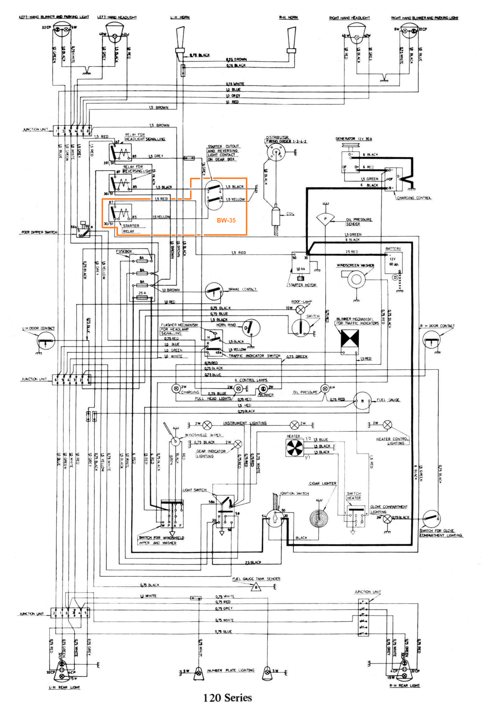